NCL Home >
Documentation >
Graphics
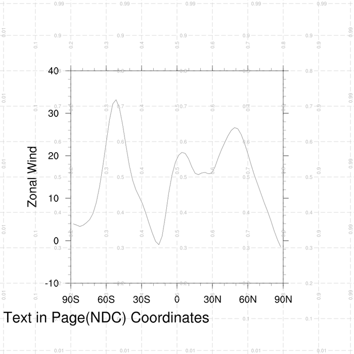
NDCs can be used when you want to position text, lines, markers, or polygons anywhere on the plotting device (that may or may not already contain a plot).
To help figure out what NDC coordinates to use for positioning text and primitives, you can use the handy drawNDCGrid procedure, which draws an NDC grid labeled with coordinate positions.
Normalized Device Coordinates (NDC)
Normalized device coordinates (NDCs) make up a coordinate system that describes positions on a virtual plotting device. The lower left corner corresponds to (0,0), and the upper right corner corresponds to (1,1).NDCs can be used when you want to position text, lines, markers, or polygons anywhere on the plotting device (that may or may not already contain a plot).
To help figure out what NDC coordinates to use for positioning text and primitives, you can use the handy drawNDCGrid procedure, which draws an NDC grid labeled with coordinate positions.
Application Examples
- text_3.ncl (view example) (drawNDCGrid example)
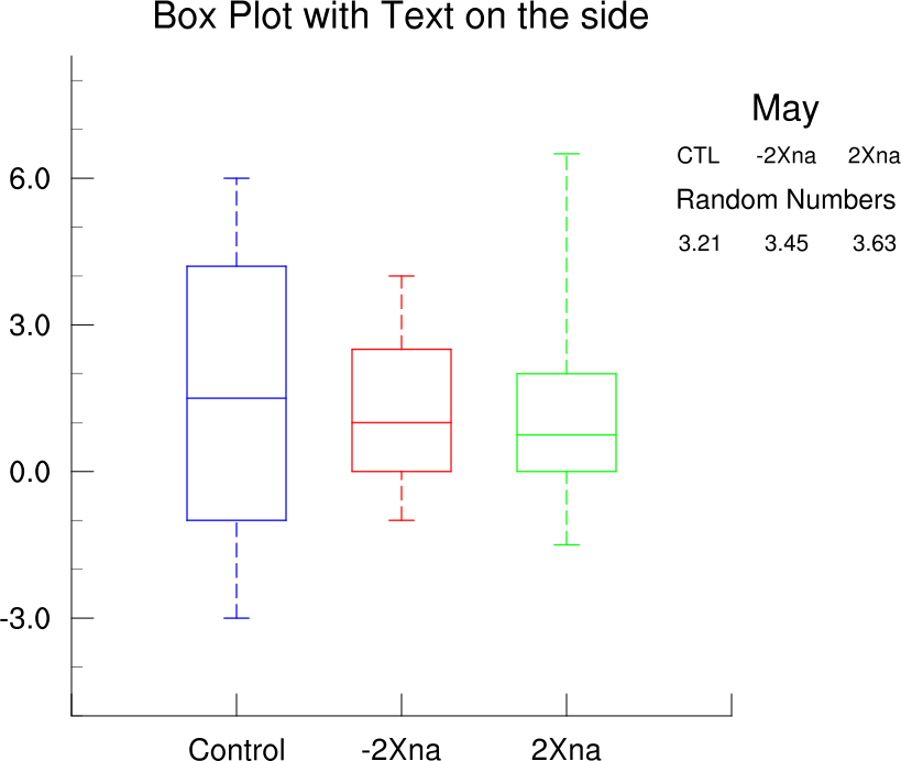
- box_4.ncl (view example)
Code Snippets
  cirx = (/ .415, .326, .225, .159, .159, .225, .326, .415, .450/)
  ciry = (/ .846, .898, .880, .801, .699, .620, .602, .654, .750/)

  gsres = True             ; Indicate you want to set some resources.
  gsres@gsFillColor = 4    ; Change fill color.

  gsn_polygon_ndc(wks,cirx,ciry,gsres)  ; Draw a filled polygon.
  frame(wks)