Alphabetical list of NCL resources
A | B | C | D | E | F | G | H | I | J | K | L | M | N | O | P | Q | R | S | T | U | V | W | X | Y | Z- amDataXF
-
When amTrackData is True, amDataXF sets the X coordinate
of the annotation item's base location.
Default: 0.0
- amDataYF
-
When amTrackData is True, amDataYF sets the Y coordinate
of the annotation item's base location.
Default: 0.0
- amJust
-
This resource of type
NhlTJustification, after
constraint to an appropriate value based on amSide, sets the
justification point of the annotation with respect to its base
location. The
PlotManager Location Control Model requires this resource to allow control of
the annotation in a manner consistent with other annotations. Note
that amJust still has an effect when amTrackData is
True. Normally, amJust is constrained based on the value of
amSide. However, if amZone is 0 or 1, or
amTrackData is True, the PlotManager does
not constrain amJust.
Note in addition that the position of the justification point is determined from the viewport of the annotation View object only. That is to say, while it is possible that View object's bounding box might be larger than its viewport, any extent outside the viewport is not considered when determining the justification point. This means that that there is the possibility of overlap if a View object has elements extending outside its own viewport along the edge closest to the PlotManager Plot viewport.
Default:
CenterCenter - amOn
-
This boolean resource specifies whether the base plot should draw the
annotation View object along with the other objects
comprising the plot.
Default: True
- amOrthogonalPosF
-
If amTrackData is False and amZone is not equal to
one, amOrthogonalPosF sets the coordinate of the base
location of the annotation orthogonal to the current amSide
and directed away from the center of the PlotManager
viewport. If amZone is equal to one, the direction
is from the viewport side specified by amSide
toward the viewport center. The
PlotManager Location Control Model requires this resource to allow control of
the annotation in a manner consistent with other annotations.
Default: 0.0
- amParallelPosF
-
If amTrackData is False, amParallelPosF specifies
the coordinate of the base location of the annotation parallel to
the current amSide and directed toward increasing NDC
values. The
PlotManager Location Control Model requires this resource to allow control of the
annotation in a manner consistent with other annotations.
Default: 0.0
- amResizeNotify
-
If this boolean resource is True, the PlotManager
sets the height and width of the annotation item whenever the size of
the base plot's viewport changes. Height is adjusted based on the
ratio of the new viewport height to the old height. Width is adjusted
based on the ratio of the new viewport width to the old width.
Default: False
- amSide
-
If amTrackData is False, this resource of type
NhlTPosition determines which of the
zone's interior sides to use as a base for establishing the coordinate
system within which the annotation is placed. The
PlotManager Location Control Model requires this resource to allow control of the
annotation in a manner consistent with other annotations. Its
value determines the origin of the coordinate system and the direction
of the positional resources, amParallelPosF and
amOrthogonalPosF. It also constrains the value of
amJust appropriately. There are four settings, which behave
as follows, unless amZone is set to one of the special zones
(0 or 1):
- NhlTOP
- The PlotManager locates the annotation relative to a line paralleling the top viewport boundary. amOrthogonalPosF increases in the direction of increasing NDC Y-Axis values and is constrained to positive values. amParallelPosF increases in the direction of increasing NDC X-Axis values. amJust is constrained to NhlBOTTOMRIGHT, NhlBOTTOMCENTER, or NhlBOTTOMLEFT.
- NhlBOTTOM
- The PlotManager locates the annotation relative to a line paralleling the bottom viewport boundary. amOrthogonalPosF increases in the direction of decreasing NDC Y-Axis values and is constrained to positive values. amParallelPosF increases in the direction of increasing NDC X-Axis values. amJust is constrained to NhlTOPRIGHT, NhlTOPCENTER, or NhlTOPLEFT.
- NhlRIGHT
- The PlotManager locates the annotation relative to a line paralleling the right viewport boundary. amOrthogonalPosF increases in the direction of increasing NDC X-Axis values and is constrained to positive values. amParallelPosF increases in the direction of increasing NDC Y-Axis values. amJust is constrained to NhlTOPLEFT, NhlCENTERLEFT, or NhlBOTTOMLEFT.
- NhlLEFT
- The PlotManager locates the annotation item relative to a line paralleling the left viewport boundary. amOrthogonalPosF increases in the direction of decreasing NDC X-Axis values and is constrained to positive values. amParallelPosF increases in the direction of increasing NDC Y-Axis values. amJust is constrained to NhlTOPRIGHT, NhlCENTERRIGHT, or NhlBOTTOMRIGHT.
Default:
Bottom - amTrackData
-
When amTrackData is set False, the PlotManager
locates the annotation View object in NDC
space using the
PlotManager Location Control Model resources amZone, amSide,
amParallelPosF, amOrthogonalPosF and
amJust. If amTrackData is True, the annotation is
positioned relative to the data coordinate space of the
base plot. In this case, the
PlotManager determines the base position of the
annotation item from the values of the resources amDataXF and
amDataYF. The resources amZone, amSide,
amParallelPosF, and amOrthogonalPosF are ignored.
However, the resource amJust still determines the
justification point of the annotation with respect to its base
location.
Default: False
- amViewId
-
You can use this resource to retrieve the id of the View
object controlled by the AnnoManager. Note that this
resource can be set only when the AnnoManager object
is created.
Default: <dynamic>
- amZone
-
If amTrackData is False, amZone specifies the
PlotManager zone assigned to the annotation.
amZone is one of the resources you must set in order to
control the location of the annotation in a manner consistent with the
rules of the
PlotManager Location Control Model. If amZone is set to 0, the annotation is
located relative to the center of the PlotManager
viewport; otherwise, it is located relative to one side of the zone's
interior boundary, which is the bounding box of the previous zone.
Default: 0
- appDefaultParent
-
This resource is only True for one
App object at a time. If it is True in
a given App object, then that
App object is the one that will be used as the
parent of any objects created with the parentid argument of
NhlCreate set to
NhlDEFAULT_APPor0.Default: <dynamic>
This resource defaults to True for the First App object created, otherwise it is False. - appFileSuffix
-
This resource is used to specify a suffix for the Application specific resource
files. It is useful to set this resource in the $(NCARG_USRRESFILE) and
$(NCARG_SYSRESFILE), if an application programmer wants to provide more than
one Application Specific Resource file. For example, if some of the end
users do not have color monitors, then there could be two resource files.
One appname.bw.res, and another appname.color.res. Then
the appFileSuffix resource can be specified to indicate which
Application specific resource file to use.
Default: .res
- appResources
-
This resource specifies an array of names. Each one of these names dynamically
becomes a valid resource for the App object. This is a very useful
feature for developers of multi-user applications because configuration
parameters for the application can become resources to the App
object. Then, users of the application can configure the application using
the same resource files that they use to configure the HLU portion
of the application.
Default: NULL
- appSysDir
-
This resource is used to indicate what directory the App
object should look in for the System application specific resource file.
Default: <dynamic>
This resource defaults to the value of the $(NCARG_SYSAPPRES) environment variable. - appUsrDir
-
This resource is used to indicate what directory the App
object should look in for the User's application specific resource file.
Default: ./ (Current Working Directory)
- caCopyArrays
-
This resource is used to determine if the CoordArrays
object should make its own copy of the caXArray and caYArray
data. If this resource is False, it is important for the programmer to keep
the data around without modifying it. However; it is more efficient--if more
dangerous--that way.
Default: True
- caXArray
-
This resource specifies the X values of the X/Y coordinate
data. It is an array of X values.
If it is a one-dimensional array, then it specifies a single vector of
X values. If it is a two-dimensional array, then
the caXCast resource is used to determine which dimension indicates
the number of vectors, and which dimension indicates the number of elements
within each vector.
If the caXArray resource is not set, then all of the
Y values set with the caYArray resource will be
paired with their integer array index. For example, assuming caYCast
is
MultipleVectorsand C syntax:(1, yarray[0][0]) (2, yarray[0][1]) (N, yarray[0][N-1])If the caXArray resource is not set, then the caYArray resource must be set.
Default: NULL
- caXCast
-
This resource is used to tell the CoordArrays object how
to interpret the caXArray resource. The three valid values are:
SingleVector-
The value
SingleVectorindicates that the caXArray provides the data for a single vector. This vector will be reused to match every vector specified by the caYArray. If the caXArray resource is set with a one-dimensional array, then the entire array will be used for the vector. If the caXArray resource is set with a two-dimensional array, then the vector will be made up from the values in the fastest-changing dimension. For example, in pseudo C array notation:
In pseudo Fortran array notation:float xarray[0][0-(N-1)];
WhereREAL XARR(1-N,1)Nis the length of the given dimension. MultipleVectors-
The value
MultipleVectorsindicates that if the caXArray resource is set with a one-dimensional array, then the entire array is used to specify a single vector that is not reused. If the caXArray resource is set with a two-dimensional array, then the caXArray has the array ordered such that the fastest-changing dimension contains the elements of each vector, and the other dimension contains the vectors. For example, in pseudo C array notation:
In pseudo Fortran array notation:float xarray[NUM_VECTORS][NUM_ELEMENTS];REAL XARR(NUM_ELEMENTS,NUM_VECTORS) SplitVectors-
The value
SplitVectorsindicates that the caXArray has the array ordered such that the fastest-changing dimension contains the vectors, and the other dimension contains the elements. For example, in pseudo C array notation:
In pseudo Fortran array notation:float xarray[NUM_ELEMENTS][NUM_VECTORS];REAL XARR(NUM_VECTORS,NUM_ELEMENTS)
Default: <dynamic>
If the caXArray resource is specified with a one-dimensional array or not at all, then the default value isSingleVector. Otherwise, the default value isMultipleVectors.
NOTE: If the caXCast resource is set toSplitVectors, then the caXArray resource will need to be reordered and copied internally so it is not as efficient. - caXMaxV
-
This resource is used to tell the CoordArrays object
the maximum value contained in the caXArray resource. If it is not specified,
the CoordArrays object will compute it. This resource
has a dynamic type so that elements of any type can be set to it.
Default: <dynamic>
The value will be computed if it is not set. - caXMinV
-
This resource is used to tell the CoordArrays object
the minimum value contained in the caXArray resource. If it is not specified,
the CoordArrays object will compute it. This resource
has a dynamic type so that elements of any type can be set to it.
Default: <dynamic>
The value will be computed if it is not set. - caXMissingV
-
This resource indicates a missing value for the elements in
the caXArray resource. When the HLU library is parsing the data
in the caXArray elements, it will treat any element with this
value as missing data. This resource has a dynamic
type so that elements of any type can be set to it.
Default: None
- caYArray
-
This resource specifies the Y values of the X/Y coordinate
data. It is an array of Y values.
If it is a one-dimensional array, then it specifies a single vector of
Y values. If it is a two-dimensional array, then
the caYCast resource is used to determine which dimension indicates
the number of vectors, and which dimension indicates the number of elements
within each vector.
If the caYArray resource is not set, then all of the
X values set with the caXArray resource will be
paired with their integer array index. For example, assuming caYCast
is
MultipleVectorsand C array syntax:(xarray[0][0],1) (xarray[0][1],2) (xarray[0][N-1],N)If the caYArray resource is not set, then the caXArray resource must be set.
Default: NULL
- caYCast
-
This resource is used to tell the CoordArrays object how
to interpret the caYArray resource. The three valid values are:
SingleVector-
The value
SingleVectorindicates that the caYArray provides the data for a single vector. This vector will be reused to match every vector specified by the caXArray. If the caYArray resource is set with a one dimensional array, then the entire array will be used for the vector. If the caYArray resource is set with a two dimensional array, then the vector will be made up from the values in the fastest changing dimension. For example, in pseudo C array notation:
In pseudo Fortran array notation:float yarray[0][0-(N-1)];
WhereREAL YARR(1-N,1)Nis the length of the given dimension. MultipleVectors-
The value
MultipleVectorsindicates that if the caYArray resource is set with a one-dimensional array, then the entire array is used to specify a single vector that is not reused. If the caYArray resource is set with a two-dimensional array, then the caYArray has the array ordered such that the fastest-changing dimension contains the elements of each vector, and the other dimension contains the vectors. For example, in pseudo C array notation:
In pseudo Fortran array notation:float yarray[NUM_VECTORS][NUM_ELEMENTS];REAL YARR(NUM_ELEMENTS,NUM_VECTORS) SplitVectors-
The value
SplitVectorsindicates that the caYArray has the array ordered such that the fastest-changing dimension contains the vectors, and the other dimension contains the elements. For example, in pseudo C array notation:
In pseudo Fortran array notation:float yarray[NUM_ELEMENTS][NUM_VECTORS];REAL YARR(NUM_VECTORS,NUM_ELEMENTS)
Default: <dynamic>
If the caYArray resource is specified with a one-dimensional array or not at all, then the default value isSingleVector. Otherwise, the default value isMultipleVectors.
Note: If the caYCast resource is set toSplitVectors, then the caYArray resource will need to be reordered and copied internally so it is not as efficient. - caYMaxV
-
This resource is used to tell the CoordArrays object
the maximum value contained in the caYArrayresource. If it is not specified,
the CoordArrays object will compute it. This resource
has a dynamic type so that elements of any type can be set to it.
Default: <dynamic>
The value will be computed if it is not set. - caYMinV
-
This resource is used to tell the CoordArrays object
the minimum value contained in the caYArray resource. If it is not specified,
the CoordArrays object will compute it. This resource
has a dynamic type so that elements of any type can be set to it.
Default: <dynamic>
The value will be computed if it is not set. - caYMissingV
-
This resource indicates a missing value for elements in
the caYArray resource. When the HLU library is parsing the data
in the caYArray elements, it will treat any element with this
value as missing data. This resource has a dynamic
type so that elements of any type can be set to it.
Default: None
- cnCellFillEdgeColor
-
If cnFillMode is set to
CellFill, this resource specifies the color used to draw boundaries around the edges of the data grid cells that contain valid non-missing values. If set to the default value,Transparent, the boundaries do not appear.You can use a color index value (integer) or a named color (string).
Default:
Transparent(-1) - cnCellFillMissingValEdgeColor
-
If cnFillMode is set to
CellFill, this resource specifies the color used to draw boundaries around the edges of the data grid cells that contain missing values. If set to the default value,Transparent, the boundaries do not appear.You can use a color index value (integer) or a named color (string).
Default:
Transparent(-1) - cnConpackParams
-
This string array resource allows you limited access to a number of
parameters belonging to the LLU Conpack package, in
order to control certain plot features for which
ContourPlot does not yet have native resources. Each
element of the array is a string consisting of a Conpack parameter
name and its desired value separated by the colon character. Here is
an example of its use in a resource file:
*cnConpackParams: (/ RC1:0.05 , RC2:0.1 , RC3:0.05 , \
	PC1:7.0 , PC2:20.0 , PC3:120.0 , PC4:0.01 , PC5:0.05 , PC6:0.05 , \
	PW1:0.0 , PW2:0.0 , PW3:0.0 , PW4:0.0 /)
If set programmatically, each string element would need to quoted as appropriate for the source language. The example given above includes all the parameters that affect the density of line labels when the cnLineLabelPlacementMode is set toRandomizedorComputed. The example values should normally result in the appearance of more labels than the default settings. See the Conpack parameter descriptions for more information.Note that the only Conpack parameters accessible using the cnConpackParams resource are ones that ContourPlot does not set internally and are unlikely to have an interaction with parameters that ContourPlot does set. Here is a categorized list of the Conpack parameters that can be set using cnConpackParams:
Contour hachuring control
- HCL
- HCS
- HCF
High/low label density
- HLX
- HLY
Computedplacement mode ("Penalty scheme" in Conpack) label density- PC1
- PC2
- PC3
- PC4
- PC5
- PC6
- PW1
- PW2
- PW3
- PW4
Randomizedplacement mode ("Regular scheme" in Conpack) label density- RC1
- RC2
- RC3
Point interpolation for lines and edges
- PIC
- PIE
Note that you cannot get the value of cnConpackParams. Attempts to do so will result in an error.
Default: NULL
- cnConstFEnableFill
-
Available in version 6.2.0 and later.
If the boolean resource cnConstFEnableFill is set to True, then in most cases, constant or near-constant fields will be rendered as a filled area, rather than having the contoured area remain blank. By default, the constant field informational text box will still appear; turn it off by setting cnConstFLabelOn to False.
In the future, cnConstFEnableFill will likely default to True, with cnConstFLabelOn defaulting to False unless contour line drawing is enabled.
Default: False
- cnConstFLabelAngleF
-
- This resource specifies the angle, in degrees, of the constant field label text and its surrounding box.
Default: 0.0
- This resource specifies the angle, in degrees, of the constant field label text and its surrounding box.
- cnConstFLabelBackgroundColor
-
- This resource sets the background color used to fill the box surrounding the constant field label. If you do not want the box to be filled at all, set cnConstFLabelBackgroundColor to
Transparent(-1).You can use a color index value (integer) or a named color (string).
Default:
Background(0) - This resource sets the background color used to fill the box surrounding the constant field label. If you do not want the box to be filled at all, set cnConstFLabelBackgroundColor to
- cnConstFLabelConstantSpacingF
-
- Normally when cnLineLabelFontQuality is set to
High, the ContourPlot object writes constant field label text with proportional spacing. Setting the cnConstFLabelConstantSpacingF to a value greater than 0.0 overrides this behavior. Instead, the distance from the start of one character to the next is computed by multiplying a single standard character width by the value of cnLineLabelConstantSpacingF. When cnLineLabelConstantSpacingF has a value between 0.0 and 1.0, characters will overlap. A value of 1.0 implies, on average, no space between characters, while values increasing from 1.0 cause the space between characters to grow. This parameter is ignored when cnConstFLabelFontQuality is notHigh. Values less than 0.0 result in an error and are replaced with the default value.Default: 0.0
- Normally when cnLineLabelFontQuality is set to
- cnConstFLabelFont
-
- This resource of type NhlTFont specifies the font used to render the constant field label.
Default: "pwritx"
- This resource of type NhlTFont specifies the font used to render the constant field label.
- cnConstFLabelFontAspectF
-
- This resource determines the shape of the constant field label characters. Values increasing from 1.0 result in thinner characters. Values decreasing from 1.0 make the characters wider. Values less than or equal to 0.0 result in a WARNING message and a restoration of the default value.
Default: 1.3125
- This resource determines the shape of the constant field label characters. Values increasing from 1.0 result in thinner characters. Values decreasing from 1.0 make the characters wider. Values less than or equal to 0.0 result in a WARNING message and a restoration of the default value.
- cnConstFLabelFontColor
-
- This resource specifies the color to use for drawing constant field label text.
You can use a color index value (integer) or a named color (string).
Default: True
- This resource specifies the color to use for drawing constant field label text.
- cnConstFLabelFontHeightF
-
- This resource controls the height, in NDC units, of characters used in the text of the constant field label. The character width scales proportionally, unless you also modify the aspect ratio using the cnConstFLabelFontAspectF resource. The constant field label text height scales with changes to the viewport width, unless you explicitly set cnConstFLabelFontHeightF during the same call.
Default: <dynamic> -- 0.012 for a viewport width of 0.6
- This resource controls the height, in NDC units, of characters used in the text of the constant field label. The character width scales proportionally, unless you also modify the aspect ratio using the cnConstFLabelFontAspectF resource. The constant field label text height scales with changes to the viewport width, unless you explicitly set cnConstFLabelFontHeightF during the same call.
- cnConstFLabelFontQuality
-
- This resource of type NhlTFontQuality determines the quality of the font used to draw the ContourPlot constant field label.
Default:
High - This resource of type NhlTFontQuality determines the quality of the font used to draw the ContourPlot constant field label.
- cnConstFLabelFontThicknessF
-
- Sets the thickness of the line used to draw constant field label text. The value acts as a multiplier of a (device-dependent) unit thickness. This resource is ignored when the cnConstFLabelFont specifies a filled font (font indexes 21-22, 25-26, 29-30, and 33-37).
Default: 1.0
- Sets the thickness of the line used to draw constant field label text. The value acts as a multiplier of a (device-dependent) unit thickness. This resource is ignored when the cnConstFLabelFont specifies a filled font (font indexes 21-22, 25-26, 29-30, and 33-37).
- cnConstFLabelFormat
-
- The cnConstFLabelFormat resource is a string that specifies the printing format for the number generated from a substitution substring in the cnConstFLabelString according to the HLU Floating Point Format Specification scheme. If any of the numerical format parameters have the dynamic attribute on, the corresponding parameter in the cnMaxDataValueFormat resource determines the parameter's value. The default value uses the shorthand notation '*+' to cause all numeric format parameters to be determined dynamically.
Default: "*+^sg"
- The cnConstFLabelFormat resource is a string that specifies the printing format for the number generated from a substitution substring in the cnConstFLabelString according to the HLU Floating Point Format Specification scheme. If any of the numerical format parameters have the dynamic attribute on, the corresponding parameter in the cnMaxDataValueFormat resource determines the parameter's value. The default value uses the shorthand notation '*+' to cause all numeric format parameters to be determined dynamically.
- cnConstFLabelFuncCode
-
- This resource of type NhlTCharacter sets the function code character that the low level utilities will use when parsing the constant field label string.
Note: the default function code was a colon (:) in NCL Versions 6.0.0 and earlier.
Default: ~
- This resource of type NhlTCharacter sets the function code character that the low level utilities will use when parsing the constant field label string.
- cnConstFLabelJust
-
- This resource of type NhlTJustification, after constraint to an appropriate value based on cnConstFLabelSide, sets the justification of the constant field label annotation with respect to its base location. The PlotManager Location Control Model requires this resource to allow control of the constant field label consistent with other annotations.
Default:
CenterCenter - This resource of type NhlTJustification, after constraint to an appropriate value based on cnConstFLabelSide, sets the justification of the constant field label annotation with respect to its base location. The PlotManager Location Control Model requires this resource to allow control of the constant field label consistent with other annotations.
- cnConstFLabelOn
-
- The ContourPlot object draws a constant field label annotation only when cnConstFLabelOn is set True and the ScalarField data are determined to have a single constant value within the limits of the available precision or when no ScalarField data are supplied.
Default: True
- The ContourPlot object draws a constant field label annotation only when cnConstFLabelOn is set True and the ScalarField data are determined to have a single constant value within the limits of the available precision or when no ScalarField data are supplied.
- cnConstFLabelOrthogonalPosF
-
- cnConstFLabelOrthogonalPosF sets the coordinate of the base location of the constant field label annotation orthogonal to the current cnConstFLabelSide and directed away from the center of the viewport. The PlotManager Location Control Model requires this resource to allow control of the constant field label consistent with other annotations.
Default: 0.0
- cnConstFLabelOrthogonalPosF sets the coordinate of the base location of the constant field label annotation orthogonal to the current cnConstFLabelSide and directed away from the center of the viewport. The PlotManager Location Control Model requires this resource to allow control of the constant field label consistent with other annotations.
- cnConstFLabelParallelPosF
-
- cnConstFLabelParallelPosF specifies the coordinate of the base location of the constant field label annotation parallel to the current cnConstFLabelSide and directed toward increasing NDC values. The PlotManager Location Control Model requires this resource to allow control of the constant field label consistent with other annotations.
Default: 0.0
- cnConstFLabelParallelPosF specifies the coordinate of the base location of the constant field label annotation parallel to the current cnConstFLabelSide and directed toward increasing NDC values. The PlotManager Location Control Model requires this resource to allow control of the constant field label consistent with other annotations.
- cnConstFLabelPerimColor
-
- This resource sets the color to use for drawing the perimeter of the constant field label box.
You can use a color index value (integer) or a named color (string).
Default:
Foreground(1) - This resource sets the color to use for drawing the perimeter of the constant field label box.
- cnConstFLabelPerimOn
-
- cnConstFLabelPerimOn is a boolean resource that determines whether ContourPlot will draw an outline around the perimeter of the box surrounding the contour constant field label. If set False, no outline will be drawn.
Default: True
- cnConstFLabelPerimOn is a boolean resource that determines whether ContourPlot will draw an outline around the perimeter of the box surrounding the contour constant field label. If set False, no outline will be drawn.
- cnConstFLabelPerimSpaceF
-
- cnConstFLabelPerimSpaceF determines the spacing or margin between the text of the constant field label and the edge of the constant field label box as a fraction of the current label text height.
Default: 0.33
- cnConstFLabelPerimSpaceF determines the spacing or margin between the text of the constant field label and the edge of the constant field label box as a fraction of the current label text height.
- cnConstFLabelPerimThicknessF
-
- This resource determines the thickness of the perimeter line around the constant field label box. The value acts as a multiplier of a (device-dependent) unit thickness.
Default: 1.0
- This resource determines the thickness of the perimeter line around the constant field label box. The value acts as a multiplier of a (device-dependent) unit thickness.
- cnConstFLabelSide
-
- This resource of type NhlTPosition determines where to place the constant field annotation in relation to the sides of the plot object. The PlotManager Location Control Model requires this resource to allow control of the constant field label consistent with other annotations. Its value determines a coordinate system origin and the direction of the positional resources, cnConstFLabelParallelPosF and cnConstFLabelOrthogonalPosF. It also constrains the value of the cnConstFLabelJust appropriately. There are four settings, which behave as follows, unless cnConstFLabelZone is set to one of the special zones (0 or 1):
Top- PlotManager locates the constant field label
annotation relative to a line that parallels the top viewport boundary.
cnConstFLabelOrthogonalPosF increases in the direction of
increasing NDC Y-Axis values and is constrained to positive values.
cnConstFLabelParallelPosF increases in the direction of
increasing NDC X-Axis values. cnConstFLabelJust is
constrained to
BottomRight,BottomCenter, orBottomLeft. Bottom- PlotManager locates the constant field label
annotation relative to a line that parallels the bottom viewport
boundary. cnConstFLabelOrthogonalPosF increases in the
direction of decreasing NDC Y-Axis values and is constrained to
positive values. cnConstFLabelParallelPosF increases in the
direction of increasing NDC X-Axis values. cnConstFLabelJust
is constrained to
TopRight,TopCenter, orTopLeft. Right- PlotManager locates the constant field label
annotation relative to a line that parallels the right viewport
boundary. cnConstFLabelOrthogonalPosF increases in the
direction of increasing NDC X-Axis values and is constrained to
positive values. cnConstFLabelParallelPosF increases in the
direction of increasing NDC Y-Axis values. cnConstFLabelJust
is constrained to
TopLeft,CenterLeft, orBottomLeft. Left- PlotManager locates the constant field label
annotation relative to a line that parallels the left viewport boundary.
cnConstFLabelOrthogonalPosF increases in the direction of
decreasing NDC X-Axis values and is constrained to positive values.
cnConstFLabelParallelPosF increases in the direction of
increasing NDC Y-Axis values. cnConstFLabelJust is
constrained to
TopRight,CenterRight, orBottomRight.
Default:
Bottom - This resource of type NhlTPosition determines where to place the constant field annotation in relation to the sides of the plot object. The PlotManager Location Control Model requires this resource to allow control of the constant field label consistent with other annotations. Its value determines a coordinate system origin and the direction of the positional resources, cnConstFLabelParallelPosF and cnConstFLabelOrthogonalPosF. It also constrains the value of the cnConstFLabelJust appropriately. There are four settings, which behave as follows, unless cnConstFLabelZone is set to one of the special zones (0 or 1):
- cnConstFLabelString
-
- Specifies the string to use when drawing a constant field label. The string may contain function codes and/or substitution substrings. ContourPlot will replace the substring $ZDV$ with a number representing the constant field value. cnConstFLabelFormat determines the format of the number; its value will be scaled based on the value of cnLabelScaleFactorF.
Default: "CONSTANT FIELD - VALUE IS $ZDV$"
- Specifies the string to use when drawing a constant field label. The string may contain function codes and/or substitution substrings. ContourPlot will replace the substring $ZDV$ with a number representing the constant field value. cnConstFLabelFormat determines the format of the number; its value will be scaled based on the value of cnLabelScaleFactorF.
- cnConstFLabelTextDirection
-
- This resource of type NhlTTextDirection specifies the direction of the text in the constant field label. The choices are:
Down- Each character is placed below the previous character in the text string.
Across- Each character is placed to the right of the previous character in the text string.
Default:
Across - This resource of type NhlTTextDirection specifies the direction of the text in the constant field label. The choices are:
- cnConstFLabelZone
-
- ContourPlot implements the constant field label as an embedded annotation. cnConstFLabelZone specifies the PlotManager zone assigned to the constant field annotation. The PlotManager Location Control Model requires this resource to allow control of the constant field label consistent with other annotations. If cnConstFLabelZone is set to 0, the positional origin is the center of the plot viewport; otherwise it is on or outside one of the sides of the viewport.
If you create a ContourPlot object without an active PlotManager by setting tfPlotManagerOn False, then ContourPlot manages the constant field annotation by itself. In this case, the cnConstFLabelZone resource is not as meaningful.
Default: 0
- ContourPlot implements the constant field label as an embedded annotation. cnConstFLabelZone specifies the PlotManager zone assigned to the constant field annotation. The PlotManager Location Control Model requires this resource to allow control of the constant field label consistent with other annotations. If cnConstFLabelZone is set to 0, the positional origin is the center of the plot viewport; otherwise it is on or outside one of the sides of the viewport.
- cnConstFUseInfoLabelRes
-
If the boolean resource cnConstFUseInfoLabelRes is set True,
all the resources applying to the constant field, except for
cnConstFLabelString, take their value from the corresponding
informational label resources.
Default: False
- cnExplicitLabelBarLabelsOn
-
- This boolean resource allows you control the labels that appear in the ContourPlot LabelBar explicitly. When set True, ContourPlot does not block the LabelBar resources lbLabelStrings and lbLabelAlignment. Therefore you can directly control both the contents of the LabelBar's label strings and their alignment with respect to the label boxes. When cnExplicitLabelBarLabelsOn is set False, ContourPlot sets both of these resources based on the current contour line labels and the value of the resource cnLabelBarEndStyle (as of version 5.0.0 or later) or (prior to version 5.0.0 or if cnLabelBarEndStyle is not set) cnLabelBarEndLabelsOn. If you set this resource True but do not set the lbLabelStrings array resource, ContourPlot will set it for you one time. This allows you to get an initial set of strings as a starting point for any customized tweaking you want to perform.
Default: False
- This boolean resource allows you control the labels that appear in the ContourPlot LabelBar explicitly. When set True, ContourPlot does not block the LabelBar resources lbLabelStrings and lbLabelAlignment. Therefore you can directly control both the contents of the LabelBar's label strings and their alignment with respect to the label boxes. When cnExplicitLabelBarLabelsOn is set False, ContourPlot sets both of these resources based on the current contour line labels and the value of the resource cnLabelBarEndStyle (as of version 5.0.0 or later) or (prior to version 5.0.0 or if cnLabelBarEndStyle is not set) cnLabelBarEndLabelsOn. If you set this resource True but do not set the lbLabelStrings array resource, ContourPlot will set it for you one time. This allows you to get an initial set of strings as a starting point for any customized tweaking you want to perform.
- cnExplicitLegendLabelsOn
-
- This boolean resource allows you control the labels that appear in the ContourPlot Legend explicitly. When set True, ContourPlot does not block the Legend resource lgLabelStrings. Therefore you can directly control the content of the Legend's label strings. When cnExplicitLegendLabelsOn is set False, ContourPlot sets lgLabelStrings based on the value of the current contour line labels. If you set this resource True but do not set the lgLabelStrings array resource, ContourPlot will set it for you one time. This allows you to get an initial set of strings as a starting point for any customized tweaking you want to perform.
Default: False
- This boolean resource allows you control the labels that appear in the ContourPlot Legend explicitly. When set True, ContourPlot does not block the Legend resource lgLabelStrings. Therefore you can directly control the content of the Legend's label strings. When cnExplicitLegendLabelsOn is set False, ContourPlot sets lgLabelStrings based on the value of the current contour line labels. If you set this resource True but do not set the lgLabelStrings array resource, ContourPlot will set it for you one time. This allows you to get an initial set of strings as a starting point for any customized tweaking you want to perform.
- cnExplicitLineLabelsOn
-
- This boolean resource controls the way ContourPlot handles the cnLineLabelStrings array resource. When set True, ContourPlot will not modify explicitly set values of the line label strings. When cnExplicitLineLabelsOn is set False, ContourPlot ignores values of cnLineLabelStrings set by the user.
Default: False
- This boolean resource controls the way ContourPlot handles the cnLineLabelStrings array resource. When set True, ContourPlot will not modify explicitly set values of the line label strings. When cnExplicitLineLabelsOn is set False, ContourPlot ignores values of cnLineLabelStrings set by the user.
- cnFillBackgroundColor
-
This resource of type
NhlTColorIndex or a named color (string)
sets the background color used for ContourPlot fill
patterns. It only has an effect for fill patterns that are neither
SolidFillnorHollowFill. By default, this resource is set toTransparent, resulting in the underlying background appearing in the spaces between the elements of the fill pattern. If set to any other valid color index, the specified color will solidly fill all spaces between the fill pattern elements.Default:
Transparent(-1) - cnFillColor
-
When cnMonoFillColor is set True, this resource of type
NhlTColorIndex or a named color (string)
sets a uniform fill color for all contour fill areas.
Default:
Foreground(1) - cnFillColors
-
The elements of this array of type NhlTColorIndexGenArray
can be set using an array of color indexes, an array of
named colors, or an array
of RGB
or RGBA values. If cnMonoFillColor
is
False, each member of the array specifies the color of a contour fill area. Note that there is always one more fill area than there are contour levels. The first element of cnFillColors specifies the fill color for any region containing a data value less than the value of cnMinLevelValF, while the highest currently used element of cnFillColors specifies the fill color for regions containing data values greater than the value of cnMaxLevelValF.Although backwards compatibility is for the most part maintained, beginning with version 6.1.0, this resource supports the new 32-bit color model, as follows:
If cnFillColors is not set explicitly, its values are derived from the settings of cnFillPalette and cnSpanFillPalette, or, if cnFillPalette is not set, wkColorMap and cnSpanFillPalette. If cnSpanFillPalette is
True, the values are distributed evenly through the range of colors available from cnFillPalette or wkColorMap. Otherwise, the values are sequential. If the color indexes are derived from cnFillPalette the first color comes from element 0, whereas if they are derived from wkColorMap, the first color comes from element 2. This is because wkColorMap contains special elements (0 and 1) for theBackgroundandForegroundcolors, whereas the palette-type resources do not. If some but not all of the available elements of cnFillColors are explicitly set, the remaining elements will be determined as if cnSpanFillPalette has the valueFalse.For backwards compatibility, colors set based on wkColorMap remain indexed to the current color map associated with the workstation. Consequently, if the workstation color map is changed prior to drawing the plot, the color indexes will map into the new color map. In contrast, color indexes derived from the cnFillPalette resource always refer to a specific color regardless of changes to wkColorMap.
Default: <dynamic>
- cnFillDotSizeF
-
This resource sets a uniform dot size, in NDC
units, for the stipple dot fill
pattern. The default value of 0.0 causes the dots to be
drawn as before, using a workstation dependent minimum dot size. A
caveat is that individual dots are not clipped around the edges of
fill areas; this becomes more noticeable as the dot size increases.
Default: 0.0
- cnFillDrawOrder
-
This resource of type
NhlTDrawOrder determines
when areas of the contour plot are filled relative to the drawing of
other elements of the plot. There are three choices:
PreDraw- Fill contour areas before the standard draw phase; fill areas will be overlaid by any subsequently drawn elements.
Draw- Fill contour areas during the standard draw phase; the fill will overlay any elements drawn during the predraw phase, but will underlie elements drawn during the postdraw phase.
PostDraw- Fill contour areas after the standard draw; the fill will overlay any elements drawn during the predraw and draw phases.
Default:
Draw - cnFillMode
-
This resource of type
NhlTcnFillMode determines how ContourPlot performs fill when cnFillOn is
set True. There are three choices:
AreaFill- The area between contour levels is decomposed into polygons. The
polygons are then filled based on the applicable fill color, fill
pattern, the scale factor assigned to the pattern, and, if stipple
fill (fill pattern 17) is specified, the size of the stippling dots.
The following resources can be used to control fill features when cnFillMode is set to
AreaFill:- cnFillBackgroundColor
- cnMonoFillColor
- cnFillColor
- cnFillColors
- cnMonoFillPattern
- cnFillPattern
- cnFillPatterns
- cnFillDotSizeF
- cnMonoFillScale
- cnFillScaleF
- cnFillScales
- cnGridBoundFillColor
- cnGridBoundFillPattern
- cnGridBoundFillScaleF
- cnMissingValFillColor
- cnMissingValFillPattern
- cnMissingValFillScaleF
- cnOutOfRangeFillColor
- cnOutOfRangeFillPattern
- cnOutOfRangeFillScaleF
Currently when using
AreaFillmode, and cnScalarFieldData is specified using a MeshScalarField object, and the ContourPlot is overlaid on certain map projections, the edges of the plot may have a ragged appearance and not completely fill the projected data boundaries. RasterFill- ContourPlot generates a representation of the
data by individually assigning colors to the elements of a
two-dimensional array of rectangular cells (a raster array)
superimposed on an area bounding the data grid. With raster mode, only
solid fill is possible, and therefore resources related to fill
pattern specification have no effect. The color of each cell is
determined based on the fill color assigned to the data value at the
cell's location. If cnRasterSmoothingOn is set True, the data
value for each raster cell is interpolated from the values of data grid cells
in the neighborhood. Otherwise, each raster cell is assigned the color
associated with the grid cell within which the greatest proportion of its
area lies.
Beginning with version 6.2.0, the
RasterFillmode fully supports transparency in a manner similar to theAreaFillandCellFillmodes. Prior to version 6.2.0, if a fill index ofTransparentwas set for any cell of a raster fill plot, theBackgroundfill color was used instead.The following resources can be used to control fill features when cnFillMode is set to
RasterFill:- cnFillColors
- cnGridBoundFillColor
- cnMissingValFillColor
- cnOutOfRangeFillColor
- cnRasterSmoothingOn
- cnRasterMinCellSizeF
- cnRasterSampleFactorF
- cnRasterCellSizeF
Currently when using
RasterFillmode, and trGridType is set toTriangularMesh, and the ContourPlot is overlaid on certain map projections, the edges of the plot may have a ragged appearance and not completely fill the projected data boundaries. CellFill- ContourPlot performs cell fill by drawing filled
polygons whose edges are defined by the borders between adjacent grid
cells. If the data grid is defined using cell edges, the cell
boundaries are obtained explicitly from the coordinate
arrays.
Otherwise, the edges are assumed to pass through the halfway
points in data grid space between the cell centers. Optionally, you
may draw lines around the edges using the cell fill edge resources. As
with raster fill, pattern fill is not supported.
Beginning with version 6.2.0, the
CellFillmode supports rendering of unstructured grids, including triangular grids, quadrilateral grids that cannot be fully defined using a 2D array, and geodesic grids with 5, 6, or more sided cells. In order to render such grids, the vertices of each cell must be explicitly specified using the MeshScalarField resources sfXCellBounds and sfYCellBounds.The following resources can be used to control fill features when cnFillMode is set to
CellFill:- cnMonoFillColor
- cnFillColor
- cnFillColors
- cnMissingValFillColor
- cnCellFillEdgeColor
- cnCellFillMissingValEdgeColor
Prior to version 6.2.0, the
CellFillmode was not available when cnScalarFieldData was specified using a MeshScalarField object.
Default:
AreaFill - cnFillOn
-
This boolean resource controls whether the areas between contour levels
are filled with a solid color and/or, if the fill method permits it,
a fill pattern. You can choose between three fill methods by setting
the resource cnFillMode.
Default: False
- cnFillOpacityF
-
Available in version 6.1.0 and later.
Specifies the opacity of the fill colors of a contour plot. Give a value in the range of 0.0 (completely transparent) to 1.0 (fully opaque).
Default: 1.0
- cnFillPalette
-
Available in version 6.1.0 and later.
This resource of type NhlTColorDefinitionGenArray allows you to set a color palette from which the values assigned to cnFillColors are chosen.
You can set this resource to the string name of a predefined color map, an array of named colors, or an array of RGB or RGBA values. If you set cnFillPalette using a predefined color map, it will have two fewer elements than if you set wkColorMap using the same color map. This is because the wkColorMap resource contains special elements (0 and 1) for the
BackgroundandForegroundcolors, whereas the palette-type resources do not. Use cnSpanFillPalette to indicate whether to span the full color palette or to simply use sequentially increasing values.Default:
None - cnFillPattern
-
When cnMonoFillPattern is set True, this resource of type
NhlTFillIndex
sets a
uniform pattern for all
contour fill areas.
Default:
SolidFill - cnFillPatterns
-
If cnMonoFillPattern is False, each element of this array of
type
NhlTFillIndexGenArray
specifies the
fill pattern used
for a contour fill area. Note that there is always one more fill area
than there are contour levels. The first element of
cnFillPatterns specifies the fill pattern for any region
containing a data value less than the value of
cnMinLevelValF, while the highest currently used element of
cnFillPatterns specifies the fill pattern for regions
containing data values greater than the value of
cnMaxLevelValF. If the array is not set explicitly, the
ContourPlot object will assign sequential fill
pattern indexes (starting with fill index 1--not "SolidFill", which
is fill index 0) to each array element up to the maximum number of
existing fill patterns. Thereafter it will repeat the sequence using
modular arithmetic. If the array currently contains fewer elements
than cnLevelCount+1, more elements will be added to
the array and given values according to the same assignment scheme;
existing elements with valid fill pattern index values will not be
modified.
Default: <dynamic>
- cnFillScaleF
-
When cnMonoFillScale is True, this resource sets a uniform
scaling value for all contour fill patterns.
Default: 1.0
- cnFillScales
-
When cnMonoFillScale is False, the cnFillScales
array resource allows individual control of the scaling of the pattern
used for each contour fill area. It has no effect for solid fill (fill
pattern
"SolidFill", index 0). Values greater than 1.0 make the pattern spacing bigger than the default spacing, resulting in a fill that appears less dense. Values less than 1.0 have the opposite effect. Values less than or equal to 0.0 are invalid, generate a warning message, and are reset to the default value, 1.0.Note that there is always one more fill area than there are contour levels. If the array is not set explicitly, the ContourPlot object will assign the value 1.0 to all elements of the array. If the array currently contains fewer elements than cnLevelCount+1, more elements will be added to the array and given the same default value of 1.0; existing elements with valid fill scale index values will not be modified.
Default: 1.0 for all elements
- cnFixFillBleed
-
When cnFillOn is set True and cnFillMode is
set to
AreaFill, ContourPlot performs area fill. Occasionally, due to limitations of the area rendering algorithm, this mode of fill fails and colors "bleed" out into areas they do not belong. If you have this kind of problem with your plot, it will probably be fixed if you set the resource cnFixFillBleed to True.However, there are certain kinds of plots that have problems when cnFixFillBleed is set True, and so far there is no clear algorithm for distinguishing these. Therefore, the corrections that are applied as a result of setting cnFixFillBleed cannot be yet be unconditionally coded into ContourPlot. Eventually, it is hoped that the need for this resource will be eliminated.
Default: True (was False in NCL versions 6.0.0 and earlier)
- cnGridBoundFillColor
-
- Available in version 6.0.0 and later.
This resource sets the color to use for filling areas outside the boundaries of the data grid, but within the viewport and the projectable areas of the underlying map, if any. cnFillOn must be set to True and cnGridBoundFillPattern must have a value other than
HollowFill(-1) for this resource to have an effect.You can use a color index value (integer) or a named color (string).
Prior to version 6.2.0, if cnFillMode was set to
RasterFill, theBackgroundcolor was substituted ifTransparentwas specified for cnGridBoundFillColor. This resource is not supported for cnFillMode set toCellFill. Also note that the triangular mesh contouring algorithm does not distinguish between missing value areas and areas outside the grid boundary. Therefore if ContourPlot is given non-rectangular data or trGridType is explicitly set toTriangularMesh, the color index used will be the larger value of those assigned to the resources cnMissingValFillColor and cnGridBoundFillColor.Note that when this resource has a value other than
Transparentand cnGridBoundFillPattern has a value other thanHollowFillthe value of cnMaxPointDistanceF is ignored. The underlying parameter it normally controls is constrained to the value 0.001. This is because the grid boundary needs to be calculated more precisely in this instance in order to correctly generate the fill areas on each side of the grid boundary.Default:
Transparent(0) - Available in version 6.0.0 and later.
- cnGridBoundFillPattern
-
- Available in version 6.0.0 and later.
This resource sets the fill pattern index used to fill areas outside the boundaries of the data grid, but within the viewport and the projectable areas of the underlying map, if any. cnFillMode must be set to
AreaFill, cnFillOn must be set to True, and cnGridBoundFillColor must have a value other thanTransparent(-1) for this resource to have an effect.If cnFillMode is set to
RasterFillonlySolidFillis possible. This resource is not supported for cnFillMode set toCellFill.Note that the triangular mesh contouring algorithm does not distinguish between missing value areas and areas outside the grid boundary. Therefore if ContourPlot is given non-rectangular data or trGridType is explicitly set to
TriangularMesh, the fill index used will be the larger value of those assigned to the resources cnMissingValFillPattern and cnGridBoundFillPattern.Default:
SolidFill - Available in version 6.0.0 and later.
- cnGridBoundFillScaleF
-
- Available in version 6.0.0 and later.
The cnGridBoundFillScaleF resource controls the scaling of the pattern used for areas outside the boundaries of the data grid, but within the viewport and the projectable areas of the underlying map, if any. It has no effect for solid fill (fill pattern index
Solidor 0) or whenever fill patterns are not enabled. Values greater than 1.0 make the pattern spacing bigger than the default spacing, resulting in a fill that appears less dense. Values less than 1.0 have the opposite effect. Values less than or equal to 0.0 are invalid, generate a warning message, and are reset to the default value, 1.0.Note that the triangular mesh contouring algorithm does not distinguish between missing value areas and areas outside the grid boundary. Therefore if ContourPlot is given non-rectangular data or trGridType is explicitly set to
TriangularMesh, the fill scale used will be the value assigned to cnMissingValFillScaleF unless it is set to the default value, 1.0. In that case it will be the value assigned to cnGridBoundFillScaleF.This resource is not supported for cnFillMode set to
CellFill.Default: 1.0
- Available in version 6.0.0 and later.
- cnGridBoundPerimColor
-
- This resource sets the color to use for drawing the perimeter line around the grid boundary.
You can use a color index value (integer) or a named color (string).
Default:
Foreground(1) - This resource sets the color to use for drawing the perimeter line around the grid boundary.
- cnGridBoundPerimDashPattern
-
- This resource sets the HLU index of a dash pattern used to render the perimeter line around the grid boundary.
Default: 0
- This resource sets the HLU index of a dash pattern used to render the perimeter line around the grid boundary.
- cnGridBoundPerimOn
-
- If set True, this boolean resource specifies that a perimeter line be drawn around the grid boundary (extent of the ScalarField data) in the ContourPlot plot.
Default: False
- If set True, this boolean resource specifies that a perimeter line be drawn around the grid boundary (extent of the ScalarField data) in the ContourPlot plot.
- cnGridBoundPerimThicknessF
-
- This resource determines the thickness of the perimeter line around the grid boundary. The value acts as a multiplier of a (device-dependent) unit thickness.
Default: 1.0
- This resource determines the thickness of the perimeter line around the grid boundary. The value acts as a multiplier of a (device-dependent) unit thickness.
- cnHighLabelAngleF
-
- This resource specifies the angle, in degrees, of high label text and its surrounding box. Due to constraints imposed by the low level utilities, it also controls the angle of the low label text, even when cnLowUseHighLabelRes is set False.
Default: 0.0
- This resource specifies the angle, in degrees, of high label text and its surrounding box. Due to constraints imposed by the low level utilities, it also controls the angle of the low label text, even when cnLowUseHighLabelRes is set False.
- cnHighLabelBackgroundColor
-
- This resource sets the background color used to fill the box surrounding each high label. If you do not want the box to be filled at all, set cnHighLabelBackgroundColor to
Transparent(-1).Default:
Background(0) - This resource sets the background color used to fill the box surrounding each high label. If you do not want the box to be filled at all, set cnHighLabelBackgroundColor to
- cnHighLabelConstantSpacingF
-
- Normally when cnLineLabelFontQuality is set to
High, the ContourPlot object writes line label text with proportional spacing. Setting the cnLineLabelConstantSpacingF to a value greater than 0.0 overrides this behavior. Instead, the distance from the start of one character to the next is computed by multiplying a single standard character width by the value of cnLineLabelConstantSpacingF. When cnLineLabelConstantSpacingF has a value between 0.0 and 1.0, characters will overlap. A value of 1.0 implies, on average, no space between characters, while values increasing from 1.0 cause the space between characters to grow. This parameter is ignored when cnLineLabelFontQuality is notHigh. Values less than 0.0 result in an error and are replaced with the default value.Default: 0.0
- Normally when cnLineLabelFontQuality is set to
- cnHighLabelCount
-
- Each time a ContourPlot is drawn, the read-only resource cnHighLabelCount is updated with the number of high labels actually rendered in the plot. Until the plot is drawn for the first time cnHighLabelCount has the value 0;
Default: 0
- Each time a ContourPlot is drawn, the read-only resource cnHighLabelCount is updated with the number of high labels actually rendered in the plot. Until the plot is drawn for the first time cnHighLabelCount has the value 0;
- cnHighLabelFont
-
- This resource of type NhlTFont specifies the font used to render high labels.
Default: "pwritx"
- This resource of type NhlTFont specifies the font used to render high labels.
- cnHighLabelFontAspectF
-
- This resource determines the shape of the high label characters. Values increasing from 1.0 result in thinner characters. Values decreasing from 1.0 make the characters wider. Values less than or equal to 0.0 result in a WARNING message and a restoration of the default value.
Default: 1.3125
- This resource determines the shape of the high label characters. Values increasing from 1.0 result in thinner characters. Values decreasing from 1.0 make the characters wider. Values less than or equal to 0.0 result in a WARNING message and a restoration of the default value.
- cnHighLabelFontColor
-
- This resource specifies the color to use for the high label text. If cnHighUseLineLabelRes is True, this resource takes its value from the first element of the cnLineLabelFontColors array.
You can use a colorindex value (integer) or a named color (string).
Default:
Foreground(1) - This resource specifies the color to use for the high label text. If cnHighUseLineLabelRes is True, this resource takes its value from the first element of the cnLineLabelFontColors array.
- cnHighLabelFontHeightF
-
- This resource controls the height, in NDC units, of characters used in the text of high labels. The character width scales proportionally, unless you also modify the aspect ratio using the cnHighLabelFontAspectF resource. The high label text height scales with changes to the viewport width, unless you explicitly set cnHighLabelFontHeightF during the same call. Due to constraints imposed by the low level utilities, it also controls the font height of the low label text, even when cnLowUseHighLabelRes is set False.
Default: <dynamic> -- 0.012 for a viewport width of 0.6
- This resource controls the height, in NDC units, of characters used in the text of high labels. The character width scales proportionally, unless you also modify the aspect ratio using the cnHighLabelFontAspectF resource. The high label text height scales with changes to the viewport width, unless you explicitly set cnHighLabelFontHeightF during the same call. Due to constraints imposed by the low level utilities, it also controls the font height of the low label text, even when cnLowUseHighLabelRes is set False.
- cnHighLabelFontQuality
-
- This resource of type NhlTFontQuality determines the quality of the font used to draw ContourPlot high labels.
Default:
High - This resource of type NhlTFontQuality determines the quality of the font used to draw ContourPlot high labels.
- cnHighLabelFontThicknessF
-
- Sets the thickness of the line used to draw high label text. The value acts as a multiplier of a (device-dependent) unit thickness. This resource is ignored when the cnHighLabelFont specifies a filled font (font indexes 21-22, 25-26, 29-30, and 33-37).
Default: 1.0
- Sets the thickness of the line used to draw high label text. The value acts as a multiplier of a (device-dependent) unit thickness. This resource is ignored when the cnHighLabelFont specifies a filled font (font indexes 21-22, 25-26, 29-30, and 33-37).
- cnHighLabelFormat
-
- The cnHighLabelFormat resource is a string that specifies the printing format for the numeric portion of high labels according to the HLU Floating Point Format Specification scheme. If any of the numerical format parameters have the dynamic attribute on, the corresponding parameter in the cnMaxDataValueFormat resource determines the parameter's value. The default value uses the shorthand notation '*+' to cause all numeric format parameters to be determined dynamically.
Default: "*+^sg"
- The cnHighLabelFormat resource is a string that specifies the printing format for the numeric portion of high labels according to the HLU Floating Point Format Specification scheme. If any of the numerical format parameters have the dynamic attribute on, the corresponding parameter in the cnMaxDataValueFormat resource determines the parameter's value. The default value uses the shorthand notation '*+' to cause all numeric format parameters to be determined dynamically.
- cnHighLabelFuncCode
-
- This resource of type NhlTCharacter sets the function code character that the low level utilities will use when parsing the high label string.
Note: the default function code was a colon (:) in NCL Versions 6.0.0 and earlier.
Default: ~
- This resource of type NhlTCharacter sets the function code character that the low level utilities will use when parsing the high label string.
- cnHighLabelPerimColor
-
- This resource sets the HLU color index used to draw the perimeter of the high label box.
Default:
Foreground(1) - This resource sets the HLU color index used to draw the perimeter of the high label box.
- cnHighLabelPerimOn
-
- cnHighLabelPerimOn is a boolean resource that determines whether ContourPlot will draw an outline around the perimeter of the box surrounding contour high labels. If set False, no outline will be drawn.
Default: True
- cnHighLabelPerimOn is a boolean resource that determines whether ContourPlot will draw an outline around the perimeter of the box surrounding contour high labels. If set False, no outline will be drawn.
- cnHighLabelPerimSpaceF
-
- cnHighLabelPerimSpaceF determines the spacing or margin between the text of the high label and the edge of the high label box as a fraction of the current high label text height.
Default: 0.33
- cnHighLabelPerimSpaceF determines the spacing or margin between the text of the high label and the edge of the high label box as a fraction of the current high label text height.
- cnHighLabelPerimThicknessF
-
- This resource determines the thickness of the perimeter line around the high label box. The value acts as a multiplier of a (device-dependent) unit thickness.
Default: 1.0
- This resource determines the thickness of the perimeter line around the high label box. The value acts as a multiplier of a (device-dependent) unit thickness.
- cnHighLabelString
-
- Specifies the string to use when drawing high labels. The string may contain function codes and/or substitution substrings. ContourPlot will replace the substring "$ZDV$" with a number representing the value at the point where the label is to appear. cnHighLabelFormat determines the format of the number and cnLabelScaleFactorF determines the scaling of the actual data value.
Default: "H~B~$ZDV$~E~"
- Specifies the string to use when drawing high labels. The string may contain function codes and/or substitution substrings. ContourPlot will replace the substring "$ZDV$" with a number representing the value at the point where the label is to appear. cnHighLabelFormat determines the format of the number and cnLabelScaleFactorF determines the scaling of the actual data value.
- cnHighLabelsOn
-
- If this boolean resource is set True, ContourPlot places labels at regions representing local maximums in the dataset.
Default: False
- If this boolean resource is set True, ContourPlot places labels at regions representing local maximums in the dataset.
- cnHighLowLabelOverlapMode
-
cnHighLowLabelOverlapMode is a resource of type
NhlTcnHighLowLabelOverlapMode. It controls how high and low labels are allowed to overlap other elements of
the ContourPlot plot and has six possible settings:
IgnoreOverlap- The ContourPlot object does nothing to prevent high and low labels from overlapping other elements of the ContourPlot plot.
OmitOverHL- The ContourPlot object omits high and low labels that would overlap previously determined high or low labels.
OmitOverVP- The ContourPlot object omits high and low labels that would overlap the edge of the viewport.
OmitOverVPAndHL- The ContourPlot object omits high and low labels that would overlap the edge of the viewport or previously determined high or low labels.
AdjustVP- The ContourPlot object adjusts the position of high and low labels that would overlap the edge of the viewport enough to eliminate the problem.
AdjustVPOmitOverHL- The ContourPlot object adjusts the position of high and low labels that would overlap the edge of the viewport enough to eliminate the problem and omits high and low labels that would overlap previously determined high or low labels.
Default:
IgnoreOverlap - cnHighUseLineLabelRes
-
If the boolean resource cnHighUseLineLabelRes is set True,
all resources applying to high labels, except for
cnHighLabelString and cnHighLabelAngleF, take their
value from the corresponding line label resources.
Default: False
- cnInfoLabelAngleF
-
- This resource specifies the angle, in degrees, of the informational label text and its surrounding box.
Default: 0.0
- This resource specifies the angle, in degrees, of the informational label text and its surrounding box.
- cnInfoLabelBackgroundColor
-
- This resource sets the background color used to fill the box surrounding the informational label. If you do not want the box to be filled at all, set cnInfoLabelBackgroundColor to
Transparent(-1).You can use a color index value (integer) or a named color (string).
Default:
Background(0) - This resource sets the background color used to fill the box surrounding the informational label. If you do not want the box to be filled at all, set cnInfoLabelBackgroundColor to
- cnInfoLabelConstantSpacingF
-
- Normally when cnLineLabelFontQuality is set to
High, the ContourPlot object writes informational label text with proportional spacing. Setting the cnInfoLabelConstantSpacingF to a value greater than 0.0 overrides this behavior. Instead, the distance from the start of one character to the next is computed by multiplying a single standard character width by the value of cnLineLabelConstantSpacingF. When cnLineLabelConstantSpacingF has a value between 0.0 and 1.0, characters will overlap. A value of 1.0 implies, on average, no space between characters, while values increasing from 1.0 cause the space between characters to grow. This parameter is ignored when cnInfoLabelFontQuality is notHigh. Values less than 0.0 result in an error and are replaced with the default value.Default: 0.0
- Normally when cnLineLabelFontQuality is set to
- cnInfoLabelFont
-
- This resource of type NhlTFont specifies the font used to render the informational label.
Default: "pwritx"
- This resource of type NhlTFont specifies the font used to render the informational label.
- cnInfoLabelFontAspectF
-
- This resource determines the shape of the informational label characters. Values increasing from 1.0 result in thinner characters. Values decreasing from 1.0 make the characters wider. Values less than or equal to 0.0 result in a WARNING message and a restoration of the default value.
Default: 1.3125
- This resource determines the shape of the informational label characters. Values increasing from 1.0 result in thinner characters. Values decreasing from 1.0 make the characters wider. Values less than or equal to 0.0 result in a WARNING message and a restoration of the default value.
- cnInfoLabelFontColor
-
- This resource specifies the color to use for the informational label text.
You can use a color index value (integer) or a named color (string).
Default:
Foreground(1) - This resource specifies the color to use for the informational label text.
- cnInfoLabelFontHeightF
-
- This resource controls the height, in NDC units, of characters used in the text of the informational label. The character width scales proportionally, unless you also modify the aspect ratio using the cnInfoLabelFontAspectF resource. The info label text height scales with changes to the viewport width, unless you explicitly set cnInfoLabelFontHeightF during the same call.
Default: <dynamic> -- 0.012 for a viewport width of 0.6
- This resource controls the height, in NDC units, of characters used in the text of the informational label. The character width scales proportionally, unless you also modify the aspect ratio using the cnInfoLabelFontAspectF resource. The info label text height scales with changes to the viewport width, unless you explicitly set cnInfoLabelFontHeightF during the same call.
- cnInfoLabelFontQuality
-
- This resource of type NhlTFontQuality determines the quality of the font used to draw the ContourPlot informational label.
Default:
High - This resource of type NhlTFontQuality determines the quality of the font used to draw the ContourPlot informational label.
- cnInfoLabelFontThicknessF
-
- Sets the thickness of the line used to draw informational label text. The value acts as a multiplier of a (device-dependent) unit thickness. This resource is ignored when the cnInfoLabelFont specifies a filled font (font indexes 21-22, 25-26, 29-30, and 33-37).
Default: 1.0
- Sets the thickness of the line used to draw informational label text. The value acts as a multiplier of a (device-dependent) unit thickness. This resource is ignored when the cnInfoLabelFont specifies a filled font (font indexes 21-22, 25-26, 29-30, and 33-37).
- cnInfoLabelFormat
-
- The cnInfoLabelFormat resource is a string that specifies the printing format for the numbers generated from substitution substrings in cnInfoLabelString according to the HLU Floating Point Format Specification scheme. If any of the numerical format parameters have the dynamic attribute on, the corresponding parameter in the cnMaxDataValueFormat resource determines the parameter's value. The default value uses the shorthand notation '*+' to cause all numeric format parameters to be determined dynamically.
Default: "*+^sg"
- The cnInfoLabelFormat resource is a string that specifies the printing format for the numbers generated from substitution substrings in cnInfoLabelString according to the HLU Floating Point Format Specification scheme. If any of the numerical format parameters have the dynamic attribute on, the corresponding parameter in the cnMaxDataValueFormat resource determines the parameter's value. The default value uses the shorthand notation '*+' to cause all numeric format parameters to be determined dynamically.
- cnInfoLabelFuncCode
-
- This resource of type NhlTCharacter sets the function code character that the low level utilities will use when parsing the informational label string.
Note: the default function code was a colon (:) in NCL Versions 6.0.0 and earlier.
Default: ~
- This resource of type NhlTCharacter sets the function code character that the low level utilities will use when parsing the informational label string.
- cnInfoLabelJust
-
- This resource of type NhlTJustification, after constraint to an appropriate value based on cnInfoLabelSide, sets the justification of the informational label annotation with respect to its base location. The PlotManager Location Control Model requires this resource to allow control of the informational label consistent with other annotations.
Default:
TopRight - This resource of type NhlTJustification, after constraint to an appropriate value based on cnInfoLabelSide, sets the justification of the informational label annotation with respect to its base location. The PlotManager Location Control Model requires this resource to allow control of the informational label consistent with other annotations.
- cnInfoLabelOn
-
- If this boolean resource is set False, ContourPlot will not draw an informational label.
Default: True (False for gsn_csm contour routines when contour fill is turned on.)
- If this boolean resource is set False, ContourPlot will not draw an informational label.
- cnInfoLabelOrthogonalPosF
-
- cnInfoLabelOrthogonalPosF sets the coordinate of the base location of the informational label annotation orthogonal to the current cnInfoLabelSide and directed away from the center of the viewport. The PlotManager Location Control Model requires this resource to allow control of the informational label consistent with other annotations.
Default: 0.02
- cnInfoLabelOrthogonalPosF sets the coordinate of the base location of the informational label annotation orthogonal to the current cnInfoLabelSide and directed away from the center of the viewport. The PlotManager Location Control Model requires this resource to allow control of the informational label consistent with other annotations.
- cnInfoLabelParallelPosF
-
- cnInfoLabelParallelPosF specifies the coordinate of the base location of the informational label annotation parallel to the current cnInfoLabelSide and directed toward increasing NDC values. The PlotManager Location Control Model requires this resource to allow control of the informational label consistent with other annotations.
Default: 1.0
- cnInfoLabelParallelPosF specifies the coordinate of the base location of the informational label annotation parallel to the current cnInfoLabelSide and directed toward increasing NDC values. The PlotManager Location Control Model requires this resource to allow control of the informational label consistent with other annotations.
- cnInfoLabelPerimColor
-
- This resource sets the color to use for drawing the perimeter of the informational label box.
You can use a color index value (integer) or a named color (string).
Default:
Foreground(1) - This resource sets the color to use for drawing the perimeter of the informational label box.
- cnInfoLabelPerimOn
-
- cnInfoLabelPerimOn is a boolean resource that determines whether ContourPlot will draw an outline around the perimeter of the box surrounding a contour informational label. If set False, no outline will be drawn.
Default: True
- cnInfoLabelPerimOn is a boolean resource that determines whether ContourPlot will draw an outline around the perimeter of the box surrounding a contour informational label. If set False, no outline will be drawn.
- cnInfoLabelPerimSpaceF
-
- cnInfoLabelPerimSpaceF determines the spacing or margin between the text of the informational label and the edge of the informational label box as a fraction of the current label text height.
Default: 0.33
- cnInfoLabelPerimSpaceF determines the spacing or margin between the text of the informational label and the edge of the informational label box as a fraction of the current label text height.
- cnInfoLabelPerimThicknessF
-
- This resource determines the thickness of the perimeter line around the informational label box. The value acts as a multiplier of a (device-dependent) unit thickness.
- cnInfoLabelSide
-
- This resource of type NhlTPosition determines where to place the informational annotation in relation to the sides of the plot object. The PlotManager Location Control Model requires this resource to allow control of the informational label consistent with other annotations. Its value determines a coordinate system origin and the direction of the positional resources, cnInfoLabelParallelPosF and cnInfoLabelOrthogonalPosF. It also constrains the value of cnInfoLabelJust appropriately. There are four settings that behave as follows, unless cnInfoLabelZone is set to one of the special zones (0 or 1):
Top- PlotManager locates the informational label
annotation relative to a line paralleling the top viewport boundary.
cnInfoLabelOrthogonalPosF increases in the direction of
increasing NDC Y-Axis values and is constrained to positive values.
cnInfoLabelParallelPosF increases in the direction of
increasing NDC X-Axis values. cnInfoLabelJust is constrained
to
BottomRight,BottomCenter, orBottomLeft. Bottom- PlotManager locates the informational label
annotation relative to a line that parallels the bottom
viewport boundary. cnInfoLabelOrthogonalPosF increases in
the direction of decreasing NDC Y-Axis values and is constrained to
positive values. cnInfoLabelParallelPosF increases in the
direction of increasing NDC X-Axis values. cnInfoLabelJust is
constrained to
TopRight,TopCenter, orTopLeft. Right- PlotManager locates the informational label
annotation relative to a line that parallels the right viewport
boundary. cnInfoLabelOrthogonalPosF increases in the
direction of increasing NDC X-Axis values and is constrained to
positive values. cnInfoLabelParallelPosF increases in the
direction of increasing NDC Y-Axis values. cnInfoLabelJust is
constrained to
TopLeft,CenterLeft, orBottomLeft. Left- PlotManager locates the informational label
annotation relative to a line that parallels the left viewport boundary.
cnInfoLabelOrthogonalPosF increases in the direction of
decreasing NDC X-Axis values and is constrained to positive values.
cnInfoLabelParallelPosF increases in the direction of
increasing NDC Y-Axis values. cnInfoLabelJust is constrained
to
TopRight,CenterRight, orBottomRight.
Default:
Bottom - This resource of type NhlTPosition determines where to place the informational annotation in relation to the sides of the plot object. The PlotManager Location Control Model requires this resource to allow control of the informational label consistent with other annotations. Its value determines a coordinate system origin and the direction of the positional resources, cnInfoLabelParallelPosF and cnInfoLabelOrthogonalPosF. It also constrains the value of cnInfoLabelJust appropriately. There are four settings that behave as follows, unless cnInfoLabelZone is set to one of the special zones (0 or 1):
- cnInfoLabelString
-
- Specifies the string to use when drawing an informational label. The string may contain function codes and/or substitution substrings. ContourPlot will replace the following substrings with numeric values:
- $CIU$
- The contour interval used (value of cnLevelSpacingF)
- $CMN$
- The minimum contour level (first element of cnLevels)
- $CMX$
- The maximum contour level
- $SFU$
- The scale factor used (value of cnLabelScaleFactorF)
- $ZMN$
- The minimum data value
- $ZMX$
- The maximum data value
Default: "CONTOUR FROM $CMN$ TO $CMX$ BY $CIU$"
- Specifies the string to use when drawing an informational label. The string may contain function codes and/or substitution substrings. ContourPlot will replace the following substrings with numeric values:
- cnInfoLabelTextDirection
-
- This resource of type NhlTTextDirection specifies the direction of the text in the informational label. The choices are:
Down- Each character is placed below the previous character in the text string.
Across- Each character is placed to the right of the previous character in the text string.
Default:
Across - This resource of type NhlTTextDirection specifies the direction of the text in the informational label. The choices are:
- cnInfoLabelZone
-
- ContourPlot implements the informational label as an embedded annotation. cnInfoLabelZone specifies the PlotManager zone assigned to the informational annotation. The PlotManager Location Control Model requires this resource to allow control of the informational label consistent with other annotations. If cnInfoLabelZone is set to 0, the positional origin is the center of the plot viewport; otherwise it is on or outside one of the sides of the viewport.
If you create a ContourPlot object without an active PlotManager by setting tfPlotManagerOn False, then ContourPlot manages the informational annotation by itself. In this case, the cnInfoLabelZone resource is not as meaningful.
Default: 3
- ContourPlot implements the informational label as an embedded annotation. cnInfoLabelZone specifies the PlotManager zone assigned to the informational annotation. The PlotManager Location Control Model requires this resource to allow control of the informational label consistent with other annotations. If cnInfoLabelZone is set to 0, the positional origin is the center of the plot viewport; otherwise it is on or outside one of the sides of the viewport.
- cnLabelBarEndLabelsOn
-
- When this boolean resource is set True and cnExplicitLabelBarLabelsOn is False, ContourPlot creates labels for the two ends of the LabelBar. The label at one end will be a string representation of the minimum value in the dataset, and at the other end will be a string representation of the maximum value in the dataset. Both strings will be formatted according to the format specification in effect for the other labels provided by ContourPlot to the LabelBar.
As of version 5.0.0 or later this resource is deprecated and is overridden by cnLabelBarEndStyle when both are set at the same time.
Default: False
- When this boolean resource is set True and cnExplicitLabelBarLabelsOn is False, ContourPlot creates labels for the two ends of the LabelBar. The label at one end will be a string representation of the minimum value in the dataset, and at the other end will be a string representation of the maximum value in the dataset. Both strings will be formatted according to the format specification in effect for the other labels provided by ContourPlot to the LabelBar.
- cnLabelBarEndStyle
-
Available in version 5.0.0 and later.
This enumerated resource of type NhlTLabelBarEndStyle allows you to select from among three styles for the ends of the ContourPlot LabelBar:
IncludeOuterBoxes- The two end boxes represent the fill color and/or patterns used for areas of the plot where the data is below the minimum contour level or above the maximum contour level. The first and last labels, representing the minimum and maximum contour levels, are aligned with the interior boundaries of the outer boxes.
IncludeMinMaxLabels- The two end boxes represent the fill color and/or patterns used for areas of the plot where the data is below the minimum contour level or above the maximum contour level. The first and last labels, representing the minimum and maximum values in the field, are aligned with the exterior boundaries of the outer boxes. However, if the minimum and/or maximum field values fall within the range specified by the minimum and maximum contour levels, one or both of these labels will be set to an empty string.
ExcludeOuterBoxes- Only boxes representing fill colors and/or patterns between the minimum and maximum contour levels appear in the LabelBar. The first and last labels, representing the minimum and maximum contour levels, are aligned with the exterior boundaries of what have now become the outer boxes of the LabelBar. This setting is useful in cases where there exist maximum and minimum values that by the nature of the quantity always bound the data, e.g. probability or per cent cloud cover.
As of version 5.0.0 or later this resource overrides the now deprecated cnLabelBarEndLabelsOn when both are set at the same time.
Default:
IncludeOuterBoxes - cnLabelDrawOrder
-
This resource of type
NhlTDrawOrder determines
when contour plot labels are drawn relative to the drawing of other elements
of the plot. There are three choices:
PreDraw- Draw contour labels before the standard draw phase; the labels will be overlaid by any subsequently drawn elements.
Draw- Draw contour labels during the standard draw phase; the labels will overlay any elements drawn during the predraw phase as well as fill and contour lines drawn during the standard draw phase, but will underlie elements drawn during the postdraw phase.
PostDraw- Draw contour labels after the standard draw; the labels will overlay any elements drawn during the predraw and draw phases as well as lines and fill drawn during the postdraw phase.
Default:
Draw - cnLabelMasking
-
This resource controls whether ContourPlot lines and fill
are masked in the areas where ContourPlot labels are to
appear. When working with raster type devices, it is seldom necessary
to mask for labels, since they can be made to solidly overlay the
areas where they appear. Also there is a noticeable performance penalty when
labels are masked, so the use of this option is discouraged unless it is
necessary.
Default: False
- cnLabelScaleFactorF
-
- cnLabelScaleFactorF is a read-only resource that contains the current scale factor that applies to ContourPlot object labels. Multiplying the numbers in the labels by the value of cnLabelScaleFactorF gives the actual data values the numbers represent. The ContourPlot object calculates its value based on the data value with the maximum absolute value, the current mode of the enumerated resource, cnLabelScalingMode, and perhaps the value of cnLabelScaleValueF. Its value may also be influenced by the number of significant digits specified by the format specification resource, cnMaxDataValueFormat. You may output the value of this resource in the informational label using the the substitution string "$SFU$".
Default: <dynamic>
- cnLabelScaleFactorF is a read-only resource that contains the current scale factor that applies to ContourPlot object labels. Multiplying the numbers in the labels by the value of cnLabelScaleFactorF gives the actual data values the numbers represent. The ContourPlot object calculates its value based on the data value with the maximum absolute value, the current mode of the enumerated resource, cnLabelScalingMode, and perhaps the value of cnLabelScaleValueF. Its value may also be influenced by the number of significant digits specified by the format specification resource, cnMaxDataValueFormat. You may output the value of this resource in the informational label using the the substitution string "$SFU$".
- cnLabelScaleValueF
-
- The interpretation of cnLabelScaleValueF depends on the value of the enumerated resource cnLabelScalingMode. When cnLabelScalingMode is set to
ScaleFactor, data values are divided by the value of cnLabelScaleValueF to obtain the numbers appearing in ContourPlot object labels. If cnLabelScalingMode is set toConfineToRange, the cnLabelScaleValueF represents an exclusive upper bound for the numbers used to represent the data values. For other values of cnLabelScalingMode, the cnLabelScaleValueF resource is ignored.Default: 1.0
- The interpretation of cnLabelScaleValueF depends on the value of the enumerated resource cnLabelScalingMode. When cnLabelScalingMode is set to
- cnLabelScalingMode
-
This resource of type
NhlTScalingMode
determines how to scale the numbers representing scalar field data
values in the ContourPlot object's
labels. cnLabelScalingMode applies to numbers that represent
data values in line labels, high and low labels, the informational
label, and the constant field label. There are five choices:
ScaleFactor- The ContourPlot object divides the data value by the value of cnLabelScaleValueF to obtain the number that appears in the label.
ConfineToRange- The ContourPlot object uses cnLabelScaleValueF as an exclusive upper bound. A scale factor is selected such that the number used to represent the data value with the maximum absolute value will be less than cnLabelScaleValueF, but greater than or equal to cnLabelScaleValueF divided by 10.0. As an example, setting cnLabelScaleValueF to 100.0 would result in a scaled number in the range 10.0 to 99.999....
TrimZeros- The ContourPlot object selects a scale factor such that the number representing the data value with the maximum absolute value will have the fewest possible extra zeros. If the maximum absolute value were 245000, for instance, it would scale to 245. If it were 0.000245, it would scale to 0.245. (The zero conventionally placed before the decimal point of a number less than 1.0 is not considered.)
MaxSigDigitsLeft- The ContourPlot object selects a scale factor such that the number representing the data value with the maximum absolute value will have its rightmost significant digit directly to the left of the decimal point. The number of significant digits is determined by the format string resource, cnMaxDataValueFormat.
AllIntegers- The ContourPlot object selects a scale factor such that the numbers representing labeled contour levels (as determined by examination of the values of the cnLevelFlags array) can be rendered as integers.
Default:
ScaleFactor - cnLegendLevelFlags
-
- This array resource of type NhlTcnLevelUseModeGenArray allows you to control which of the lines representing contour levels are to appear in the ContourPlot Legend. You can also control whether the lines that do appear are to get a line label. Although the type allows for four choices, this resource supports only three of them:
NoLine- Do not draw a line representing this contour level in the Legend.
LineOnly- Draw a line representing this contour level, but no label in the Legend.
LabelOnly- Currently, if an element is set to this value, it is treated the
same as if it were set to
NoLine. LineAndLabel- Draw a line representing this contour level along with a line label in the Legend.
NoLine.Default: NULL
- This array resource of type NhlTcnLevelUseModeGenArray allows you to control which of the lines representing contour levels are to appear in the ContourPlot Legend. You can also control whether the lines that do appear are to get a line label. Although the type allows for four choices, this resource supports only three of them:
- cnLevelCount
-
A read-only resource set to the actual number of levels chosen during
the level selection process.
Default: <dynamic>
- cnLevelFlag
-
When cnMonoLevelFlag is set True, this resource of type
NhlTcnLevelUseMode
sets the rendering of all contour levels to one of four possible
values:
NoLine- No lines or labels appear.
LineOnly- Lines but no labels appear.
LabelOnly- Labels but no lines appear.
LineAndLabel- Both lines and labels appear.
Default:
LineOnly - cnLevelFlags
-
When cnMonoLevelFlag is False, cnLevelFlags is an
array of type
NhlTcnLevelUseModeGenArray
that allows you individual control over whether a line and/or a line
label is to appear at each contour level. It has no effect on contour
fill. There are four choices:
NoLine- No lines or labels appear at the contour level.
LineOnly- Lines but no labels appear at the contour level.
LabelOnly- Labels but no lines appear at the contour level.
LineAndLabel- Both lines and labels appear at the contour level.
If cnMonoLevelFlag is False and you do not explicitly set cnLevelFlags, the ContourPlot object will set its elements for you based on the value of cnLineLabelInterval. Elements will be set to
LineOnlyexcept that if cnLineLabelInterval is greater than 0, elements separated by the interval of cnLineLabelInterval will be set toLineAndLabel. This effect will occur both at initialization and any time you explicitly set cnLineLabelInterval.Default: <dynamic>
- cnLevelSelectionMode
-
This enumerated resource of type
NhlTLevelSelectionMode
provides four methods for selecting the contour intervals displayed in
a plot:
AutomaticLevels- Ordinarily this mode determines contour levels by picking a
spacing value from a set of relatively "round" numbers scaled by
powers of 10 to the range of the data. This set of numbers is as
follows: 1.0, 2.0, 2.5, 4.0, 5.0. The number of levels chosen will be
as close as possible to the value of cnMaxLevelCount without
exceeding it. Once the spacing is chosen, the minimum contour level is
set to the value of the least multiple of the spacing greater than the
minimum data value. Likewise the maximum contour level becomes the
greatest multiple of the spacing less than the maximum data value.
Based on these values, ContourPlot sets the resources
cnLevelSpacingF, cnMinLevelValF, and
cnMaxLevelValF appropriately.
On the other hand, if you explicitly set the resource cnLevelSpacingF to a valid value greater than 0.0 and less than the range of the data, it will be used as the interval spacing. The minimum and maximum levels are calculated as before. If as a consequence, cnMaxLevelCount is less than the number of levels so specified, it will be set to the number of levels actually needed. However, if the choice of spacing causes the absolute maximum number of levels, currently 255, to be exceeded, ContourPlot will issue a warning message and recalculate the spacing as previously described.
In any case, ContourPlot sets the elements of the array resource cnLevels to the values of the contour levels chosen and the read-only resource cnLevelCount to the number of levels.
ManualLevelsManualLevelsmode bases the choice of contour levels on the values of the resources cnLevelSpacingF, cnMinLevelValF, and cnMaxLevelValF. Starting at cnMinLevelValF, contour levels are created at intervals spaced by the value of cnLevelSpacingF until cnMaxLevelValF is reached. The final contour level will always be cnMaxLevelValF. ContourPlot sets elements of the array resource cnLevels to the values of each contour level chosen and the read-only resource cnLevelCount to the number of levels. If the current value of cnMaxLevelCount is less than cnLevelCount, it is reset to the value of cnLevelCount. However, if the level count would exceed the absolute maximum number of levels, currently 255, ContourPlot issues a warning and chooses a new value of cnLevelSpacingF based on the value of cnMaxLevelCount.If you choose
ManualLevelsselection mode when the ContourPlot object is created, and if you do not set cnMinLevelValF, ContourPlot will choose levels as if you had setAutomaticLevelsmode. If you set cnMinLevelValF only, a default spacing is used, and the value of cnMaxLevelValF is determined as it would be forAutomaticLevelsmode.ExplicitLevels- This mode allows you to specify the value of each contour level by
explicitly setting the contents of the cnLevels array. If
you choose
ExplicitLevelsselection mode when creating a ContourPlot object, but do not specify the contents of the cnLevels array, ContourPlot will choose levels as if you had specifiedAutomaticLevelsmode. Thereafter, when you setExplicitLevelsmode, ContourPlot uses the current contents of cnLevels, whether or not you set it explicitly.If the number of elements in cnLevels exceeds the absolute maximum number of levels (currently 255), ContourPlot issues a warning and the mode defaults to
AutomaticLevels. Note that ContourPlot always sorts the elements of cnLevels into a monotonically increasing sequence. After sorting, cnMinLevelValF is set equal to the value of first element of cnLevels, and cnMaxLevelValF is set to the value of the last element. cnLevelSpacingF is set to the average value of the spacing separating each level. EqualSpacedLevels- For this mode, ContourPlot divides the range
spanning the dataset minimum and maximum values into
cnMaxLevelCount+1 equally spaced
intervals.
ContourPlot sets cnLevelSpacingF to the value of this interval, cnMinLevelValF to the dataset minimum plus the value of cnLevelSpacingF, and cnMaxLevelValF to the value of the dataset maximum minus the value of cnLevelSpacingF. You cannot set these three resources yourself.
ContourPlot also sets the read-only resource cnLevelCount equal to cnMaxLevelCount.
Default:
AutomaticLevels - cnLevelSpacingF
-
When the cnLevelSelectionMode is
ManualLevelsor when the cnLevelSelectionMode isAutomaticLevels, and cnLevelSpacingF is explicitly set, cnLevelSpacingF determines the spacing between contour intervals. Otherwise, the ContourPlot object sets the value of cnLevelSpacingF based on the contour levels actually chosen. When the cnLevelSelectionMode isExplicitLevels, cnLevelSpacingF will be set to the arithmetic average of the spacing between levels.Default: 5.0
- cnLevels
-
An array of floats containing the contour levels used to render the
contour plot. If the cnLevelSelectionMode is
ExplicitLevels, you may set these values yourself. Otherwise, the ContourPlot object sets the elements of this array.Default: <dynamic>
- cnLineColor
-
When cnMonoLineColor is set True, this resource of
type NhlTColorIndex or a
named color (string). sets a
uniform color for all contour lines.
Default:
Foreground(1) - cnLineColors
-
The elements of this array of type NhlTColorIndexGenArray
can be set using an array of color indexes, an array of
named colors, or an array
of RGB
or RGBA values. If cnMonoFillColor
If cnMonoLineColor is
False, each member of the array specifies the color of the contour line drawn at the corresponding contour level.Although backwards compatibility is for the most part maintained, beginning with version 6.1.0, this resource supports the new 32-bit color model, as follows:
If cnLineColors is not set explicitly, its values are derived from the settings of cnLinePalette and cnSpanLinePalette, or, if cnLinePalette is not set, wkColorMap and cnSpanLinePalette. If cnSpanLinePalette is
True, the values are distributed evenly through the range of colors available from cnLinePalette or wkColorMap. Otherwise, the values are sequential. If the color indexes are derived from cnLinePalette the first color comes from element 0, whereas if they are derived from wkColorMap, the first color comes from element 2. This is because wkColorMap contains special elements (0 and 1) for theBackgroundandForegroundcolors, whereas the palette-type resources do not. If some but not all of the available elements of cnLineColors are explicitly set, the remaining elements will be determined as if cnSpanLinePalette has the valueFalse.For backwards compatibility, colors set based on wkColorMap remain indexed to the current color map associated with the workstation. Consequently, if the workstation color map is changed prior to drawing the plot, the color indexes will map into the new color map. In contrast, color indexes derived from the cnLinePalette resource always refer to a specific color regardless of changes to wkColorMap.
Default: <dynamic>
- cnLineDashPattern
-
When cnMonoLineDashPattern is set True, this resource of type
NhlTDashIndex
sets a uniform
dash pattern for all contour lines.
Default:
SolidLine(0) - cnLineDashPatterns
-
When cnMonoLineDashPattern is False, this array resource of
type
NhlTDashIndexGenArray
individually sets the
dash pattern of a contour line drawn at the corresponding contour
level. If the array is not set explicitly, the
ContourPlot object will assign sequential dash
pattern indexes to each array element--starting with dash pattern
index 1, not
"SolidLine"(0)--up to the maximum number of existing dash patterns. Thereafter, it will repeat the sequence using modular arithmetic. If the array currently contains fewer elements than cnLevelCount, more elements will be added to the array and given values according to the same assignment scheme; existing elements with valid dash pattern index values will not be modified.Default: <dynamic>
- cnLineDashSegLenF
-
This resource indicates the length of each segment of the dash patterns
used to draw contour lines. It is the length in NDC
units before the dash pattern repeats itself. If
cnLineLabelPlacementMode is set to
Constantthe line labels are rendered as part of the dash pattern, and therefore cnLineDashSegLenF also controls the spacing between the line labels.cnLineDashSegLenF automatically scales with changes in the size of the viewport of the ContourPlot object. ContourPlot sets its default value dynamically based on the ratio of the actual plot viewport width to the reference viewport width.
Default: 0.15 (for a viewport width of 0.6)
- cnLineDrawOrder
-
This resource of type
NhlTDrawOrder determines
when the contour lines are drawn relative to other elements of the
plot. There are three choices:
PreDraw- Draw the contour lines before the standard draw; the lines will be overlaid by any subsequently drawn elements.
Draw- Draw the lines during the standard draw; the lines will overlay any elements drawn during the predraw phase, but will underlie elements drawn during the postdraw phase.
PostDraw- Draw the lines after the standard draw; the lines will overlay any elements drawn during the predraw and draw phases.
Default:
Draw - cnLineLabelAngleF
-
- When cnLineLabelAngleF has a value less than 0.0, ContourPlot line labels are angled in the direction of the tangent of the contour line at the location of the label. Otherwise, cnLineLabelAngleF specifies the angle, in degrees, of all contour line labels. If cnLineLabelPlacementMode is set to
Constant, this resource has no effect: the line labels are always placed along the contour line.Default: -1.0
- When cnLineLabelAngleF has a value less than 0.0, ContourPlot line labels are angled in the direction of the tangent of the contour line at the location of the label. Otherwise, cnLineLabelAngleF specifies the angle, in degrees, of all contour line labels. If cnLineLabelPlacementMode is set to
- cnLineLabelBackgroundColor
-
- This resource sets the background color used to fill the box surrounding each line label. If you do not want the box to be filled at all, set cnLineLabelBackgroundColor to
Transparent(-1). If cnLineLabelPlacementMode is set toConstant, this resource has no effect: a boxed background is not available.You can use a color index value (integer) or a named color (string).
Default:
Background(0) - This resource sets the background color used to fill the box surrounding each line label. If you do not want the box to be filled at all, set cnLineLabelBackgroundColor to
- cnLineLabelConstantSpacingF
-
- Normally when cnLineLabelFontQuality is set to
High, the ContourPlot object writes line label text with proportional spacing. Setting the cnLineLabelConstantSpacingF to a value greater than 0.0 overrides this behavior. Instead, the distance from the start of one character to the next is computed by multiplying a single standard character width by the value of cnLineLabelConstantSpacingF. When cnLineLabelConstantSpacingF has a value between 0.0 and 1.0, characters will overlap. A value of 1.0 implies, on average, no space between characters, while values increasing from 1.0 cause the space between characters to grow. This parameter is ignored when cnLineLabelFontQuality is notHigh. Values less than 0.0 result in an error and are replaced with the default value.Default: 0.0
- Normally when cnLineLabelFontQuality is set to
- cnLineLabelCount
-
- Each time a ContourPlot is drawn, the read-only resource cnLineLabelCount is updated with the number of line labels actually rendered in the plot. Until the plot is drawn for the first time cnLineLabelCount has the value 0;
Default: 0
- Each time a ContourPlot is drawn, the read-only resource cnLineLabelCount is updated with the number of line labels actually rendered in the plot. Until the plot is drawn for the first time cnLineLabelCount has the value 0;
- cnLineLabelDensityF
-
- The cnLineLabelDensityF resource provides simple, though not very precise, control over the number of line labels that appear in a contourplot. It has an effect only when cnLineLabelPlacementMode is set to
ComputedorRandomized. cnLineDashSegLenF controls the density ofConstantmode line labels..If cnLineLabelDensityF is set to its default value, 0.0, it has no effect and line label density can only be controlled by setting the appropriate low level parameters via the resource cnConpackParams. Setting cnLineLabelDensityF to 1.0 causes ContourPlot to use the default settings of the applicable low level resources, overriding any that are set through the cnConpackParams resource. Increase the number of line labels by setting cnLineLabelDensityF to values greater than 1.0, or decrease the number by setting it to positive values less than 1.0. You can obtain a count of the line labels drawn in the most recent rendering of the ContourPlot by retrieving the resource cnLineLabelCount.
Default: 0.0
- The cnLineLabelDensityF resource provides simple, though not very precise, control over the number of line labels that appear in a contourplot. It has an effect only when cnLineLabelPlacementMode is set to
- cnLineLabelFont
-
- This resource of type NhlTFont specifies the font used to render line labels.
Default: "pwritx"
- This resource of type NhlTFont specifies the font used to render line labels.
- cnLineLabelFontAspectF
-
- This resource determines the shape of the line label characters. Values increasing from 1.0 result in thinner characters. Values decreasing from 1.0 make the characters wider. Values less than or equal to 0.0 result in a WARNING message and a restoration of the default value.
Default: 1.3125
- This resource determines the shape of the line label characters. Values increasing from 1.0 result in thinner characters. Values decreasing from 1.0 make the characters wider. Values less than or equal to 0.0 result in a WARNING message and a restoration of the default value.
- cnLineLabelFontColor
-
- When cnMonoLineLabelFontColor is set True, this resource of type NhlTColorIndex or a named color (string) sets a uniform color for all contour line labels.
Default:
Foreground(1) - When cnMonoLineLabelFontColor is set True, this resource of type NhlTColorIndex or a named color (string) sets a uniform color for all contour line labels.
- cnLineLabelFontColors
-
- When cnMonoLineLabelFontColor is False, each element of this array of type NhlTColorIndexGenArray or named color (string) specifies the color of a contour line label. If the array is not set explicitly, it will dynamically default to a set of colors spread numerically over the range of defined HLU color indexes. The colors used will therefore depend on the number of contour levels. If the array currently contains fewer elements than cnLevelCount, more elements will be added to the array and given values according to the default color assignment scheme; existing elements with valid color index values will not be modified.
You can use an array of color index values (integer) or named colors (string).
Default: <dynamic>
- When cnMonoLineLabelFontColor is False, each element of this array of type NhlTColorIndexGenArray or named color (string) specifies the color of a contour line label. If the array is not set explicitly, it will dynamically default to a set of colors spread numerically over the range of defined HLU color indexes. The colors used will therefore depend on the number of contour levels. If the array currently contains fewer elements than cnLevelCount, more elements will be added to the array and given values according to the default color assignment scheme; existing elements with valid color index values will not be modified.
- cnLineLabelFontHeightF
-
- This resource controls the height, in NDC units, of characters used in the text of line labels. The character width scales proportionally, unless you also modify the aspect ratio using the cnLineLabelFontAspectF resource. The line label text height scales with changes to the viewport width, unless you explicitly set cnLineLabelFontHeightF during the same call.
Default: <dynamic> -- 0.012 for a viewport width of 0.6
- This resource controls the height, in NDC units, of characters used in the text of line labels. The character width scales proportionally, unless you also modify the aspect ratio using the cnLineLabelFontAspectF resource. The line label text height scales with changes to the viewport width, unless you explicitly set cnLineLabelFontHeightF during the same call.
- cnLineLabelFontQuality
-
- This resource of type NhlTFontQuality determines the quality of the font used to draw ContourPlot line labels.
Default:
High - This resource of type NhlTFontQuality determines the quality of the font used to draw ContourPlot line labels.
- cnLineLabelFontThicknessF
-
- Sets the thickness of the line used to draw line label text. The value acts as a multiplier of a (device-dependent) unit thickness. This resource is ignored when the cnLineLabelFont specifies a filled font (font indexes 21-22, 25-26, 29-30, and 33-37).
Default: 1.0
- Sets the thickness of the line used to draw line label text. The value acts as a multiplier of a (device-dependent) unit thickness. This resource is ignored when the cnLineLabelFont specifies a filled font (font indexes 21-22, 25-26, 29-30, and 33-37).
- cnLineLabelFormat
-
- The cnLineLabelFormat resource is a string that specifies the printing format for the numeric portion of line labels according to the HLU Floating Point Format Specification scheme. It does not apply when the user explicitly sets the elements of cnLineLabelStrings. If any of the numerical format parameters have the dynamic attribute on, the corresponding parameter in the cnMaxDataValueFormat resource determines the parameter's value. The default value uses the shorthand notation '*+' to cause all numeric format parameters to be determined dynamically.
Note that since the labels used for the ContourPlot LabelBar are copied from the cnLineLabelStrings resource the cnLineLabelFormat resource also controls the formatting of the LabelBar labels. This is true whether cnLineLabelsOn is set
TrueorFalse.Default: "*+^sg"
- The cnLineLabelFormat resource is a string that specifies the printing format for the numeric portion of line labels according to the HLU Floating Point Format Specification scheme. It does not apply when the user explicitly sets the elements of cnLineLabelStrings. If any of the numerical format parameters have the dynamic attribute on, the corresponding parameter in the cnMaxDataValueFormat resource determines the parameter's value. The default value uses the shorthand notation '*+' to cause all numeric format parameters to be determined dynamically.
- cnLineLabelFuncCode
-
- This resource of type NhlTCharacter sets the function code character that the low level utilities will use when parsing the label string.
Note: the default function code was a colon (:) in NCL Versions 6.0.0 and earlier.
Default: ~
- This resource of type NhlTCharacter sets the function code character that the low level utilities will use when parsing the label string.
- cnLineLabelInterval
-
When cnMonoLevelFlag is False and you do not explicitly set
the array cnLevelFlags, a positive value of
cnLineLabelInterval sets the number of levels from a labeled
level to the next labeled level. The interval is generated in both
directions from the contour level requiring the least number of
significant digits to express (with the value 0.0 considered to
require zero significant digits). If cnLineLabelInterval is
less than or equal to zero, then no contour levels are labeled.
Default: 2
- cnLineLabelPerimColor
-
- This resource sets the HLU color index used to draw the perimeter of the line label box. If cnLineLabelPlacementMode is set to
Constant, this resource has no effect: no perimeter can be drawn around the label.You can use a color index value (integer) or a named color (string).
Default:
Foreground(1) - This resource sets the HLU color index used to draw the perimeter of the line label box. If cnLineLabelPlacementMode is set to
- cnLineLabelPerimOn
-
- cnLineLabelPerimOn is a boolean resource that determines whether ContourPlot will draw an outline around the perimeter of the box surrounding contour line labels. If set False, no outline will be drawn. If cnLineLabelPlacementMode is set to
Constant, this resource has no effect: no perimeter can be drawn around the label.Default: True
- cnLineLabelPerimOn is a boolean resource that determines whether ContourPlot will draw an outline around the perimeter of the box surrounding contour line labels. If set False, no outline will be drawn. If cnLineLabelPlacementMode is set to
- cnLineLabelPerimSpaceF
-
- cnLineLabelPerimSpaceF determines the spacing or margin between the text of the line label and the edge of the line label box as a fraction of the current line label text height. If cnLineLabelPlacementMode is set to
Constant, this resource has no effect: no perimeter can be drawn around the label.Default: 0.33
- cnLineLabelPerimSpaceF determines the spacing or margin between the text of the line label and the edge of the line label box as a fraction of the current line label text height. If cnLineLabelPlacementMode is set to
- cnLineLabelPerimThicknessF
-
- This resource determines the thickness of the perimeter line around the line label box. The value acts as a multiplier of a (device-dependent) unit thickness. If cnLineLabelPlacementMode is set to
Constant, this resource has no effect: no perimeter can be drawn around the label.Default: 1.0
- This resource determines the thickness of the perimeter line around the line label box. The value acts as a multiplier of a (device-dependent) unit thickness. If cnLineLabelPlacementMode is set to
- cnLineLabelPlacementMode
-
- This resource of type NhlTcnLineLabelPlacementMode determines the algorithm ContourPlot uses to place line labels. There are three choices:
Constant- ContourPlot draws line labels as an integral part of the line dash pattern. As a result, the labels are equally spaced along the lines. You can control the spacing between the labels by setting the cnLineDashSegLenF resource.
Randomized- ContourPlot places labels using a randomizing algorithm to vary the distance between labels. You can increase or decrease the overall number of labels using the cnLineLabelDensityF resource. Or for more precise control, you can specify the appropriate low level parameter values yourself using cnConpackParams.
Computed- ContourPlot uses a more complex algorithm involving the local gradient, number of contour lines in a region, cumulative change in direction, and an optimum distance value to determine the best location for line labels. This method usually gives the best-looking results. You can increase or decrease the overall number of labels using the cnLineLabelDensityF resource. Or for more precise control, you can specify the appropriate low level parameter values yourself using cnConpackParams.
Default:
Randomized - This resource of type NhlTcnLineLabelPlacementMode determines the algorithm ContourPlot uses to place line labels. There are three choices:
- cnLineLabelStrings
-
- Each element of the array resource cnLineLabelStrings specifies a string to be drawn at a contour level. Note that there is an element of this array for each contour level, whether or not (based on the contents of the cnLevelFlags array) a label will actually be drawn. If cnExplicitLineLabelsOn is set False, ContourPlot automatically sets the contents of the array to a set of strings representing the values of the contour levels, scaled based on the value of cnLabelScaleFactorF, and formatted based on the contents of cnMaxDataValueFormat and cnLineLabelFormat.
If cnExplicitLineLabelsOn is set True, ContourPlot will not modify any initialized element of the array, thus allowing you to set its values to strings of your choice. If you set the resource with an array containing fewer elements than the current number of levels, the remaining elements will be assigned using the automatic method.
Default: <dynamic>
- Each element of the array resource cnLineLabelStrings specifies a string to be drawn at a contour level. Note that there is an element of this array for each contour level, whether or not (based on the contents of the cnLevelFlags array) a label will actually be drawn. If cnExplicitLineLabelsOn is set False, ContourPlot automatically sets the contents of the array to a set of strings representing the values of the contour levels, scaled based on the value of cnLabelScaleFactorF, and formatted based on the contents of cnMaxDataValueFormat and cnLineLabelFormat.
-
- cnLineLabelsOn
-
- If this boolean resource is set False, contour line labels will not appear in the contour plot. Note that this resource overrides the values contained in the cnLevelFlags array resource with respect to line labels, but has nothing to do with whether contour lines appear.
Default: True (False for gsn_csm contour routines when contour fill is turned on.)
- If this boolean resource is set False, contour line labels will not appear in the contour plot. Note that this resource overrides the values contained in the cnLevelFlags array resource with respect to line labels, but has nothing to do with whether contour lines appear.
- cnLinePalette
-
Available in version 6.1.0 and later.
This resource of type NhlTColorDefinitionGenArray allows you to set a color palette from which the values assigned to cnLineColors are chosen.
You can set this resource to the string name of a predefined color map, an array of named colors, or an array of RGB or RGBA values. If you set cnLinePalette using a predefined color map, it will have two fewer elements than if you set wkColorMap using the same color map. This is because the wkColorMap resource contains special elements (0 and 1) for the
BackgroundandForegroundcolors, whereas the palette-type resources do not. Use cnSpanLinePalette to indicate whether to span the full color palette or to simply use sequentially increasing values.Default:
None - cnLineThicknessF
-
When cnMonoLineThickness is True, this resource sets a uniform
line thickness for all contour lines.
Default: 1.0
- cnLineThicknesses
-
If cnMonoLineThickness is False, each element of this array
resource specifies the line thickness of a contour line drawn at the
corresponding contour level. If the array is not set explicitly, all
elements default to the value 1.0. If the array currently contains
fewer elements than cnLevelCount, more elements will be added
to the array and set to the default value, 1.0; existing elements with
valid line thicknesses (greater than 0.0) will not be modified.
Default: 1.0 for all elements
- cnLinesOn
-
If this boolean resource is set False, no contour lines will appear
in the contour plot, regardless of the values contained in the
cnLevelFlags array resource. It has no effect on line labels.
Default: True (False for gsn_csm contour routines when contour fill is turned on.)
- cnLowLabelAngleF
-
- Due to constraints imposed by the low level utilities, the low label text angle cannot be set independently of the high label text angle. Therefore, this resource is currently ignored. Use cnHighLabelAngleF.
- Due to constraints imposed by the low level utilities, the low label text angle cannot be set independently of the high label text angle. Therefore, this resource is currently ignored. Use cnHighLabelAngleF.
- cnLowLabelBackgroundColor
-
- This resource sets the background color used to fill the box surrounding each low label. If you do not want the box to be filled at all, set cnLowLabelBackgroundColor to
Transparent(-1).Default:
Background(0) - This resource sets the background color used to fill the box surrounding each low label. If you do not want the box to be filled at all, set cnLowLabelBackgroundColor to
- cnLowLabelConstantSpacingF
-
- Normally when cnLineLabelFontQuality is set to
High, the ContourPlot object writes line label text with proportional spacing. Setting the cnLineLabelConstantSpacingF to a value greater than 0.0 overrides this behavior. Instead, the distance from the start of one character to the next is computed by multiplying a single standard character width by the value of cnLineLabelConstantSpacingF. When cnLineLabelConstantSpacingF has a value between 0.0 and 1.0, characters will overlap. A value of 1.0 implies, on average, no space between characters, while values increasing from 1.0 cause the space between characters to grow. This parameter is ignored when cnLineLabelFontQuality is notHigh. Values less than 0.0 result in an error and are replaced with the default value.Default: 0.0
- Normally when cnLineLabelFontQuality is set to
- cnLowLabelCount
-
- Each time a ContourPlot is drawn, the read-only resource cnLowLabelCount is updated with the number of low labels actually rendered in the plot. Until the plot is drawn for the first time cnLowLabelCount has the value 0;
Default: 0
- Each time a ContourPlot is drawn, the read-only resource cnLowLabelCount is updated with the number of low labels actually rendered in the plot. Until the plot is drawn for the first time cnLowLabelCount has the value 0;
- cnLowLabelFont
-
- This resource of type NhlTFont specifies the font used to render low labels.
Default: "pwritx"
- This resource of type NhlTFont specifies the font used to render low labels.
- cnLowLabelFontAspectF
-
- This resource determines the shape of the low label characters. Values increasing from 1.0 result in thinner characters. Values decreasing from 1.0 make the characters wider. Values less than or equal to 0.0 result in a WARNING message and a restoration of the default value.
Default: 1.3125
- This resource determines the shape of the low label characters. Values increasing from 1.0 result in thinner characters. Values decreasing from 1.0 make the characters wider. Values less than or equal to 0.0 result in a WARNING message and a restoration of the default value.
- cnLowLabelFontColor
-
- This resource specifies the HLU color index used to render low label text.
Default:
Foreground(1) - This resource specifies the HLU color index used to render low label text.
- cnLowLabelFontHeightF
-
- Due to constraints imposed by the low level utilities, the low label font height cannot be set independently of the high label font height. Therefore, this resource is currently ignored. Use cnHighLabelFontHeightF.
- Due to constraints imposed by the low level utilities, the low label font height cannot be set independently of the high label font height. Therefore, this resource is currently ignored. Use cnHighLabelFontHeightF.
- cnLowLabelFontQuality
-
- This resource of type NhlTFontQuality determines the quality of the font used to draw ContourPlot low labels.
Default:
High - This resource of type NhlTFontQuality determines the quality of the font used to draw ContourPlot low labels.
- cnLowLabelFontThicknessF
-
- Sets the thickness of the line used to draw low label text. The value acts as a multiplier of a (device-dependent) unit thickness. This resource is ignored when the cnLowLabelFont specifies a filled font (font indexes 21-22, 25-26, 29-30, and 33-37).
Default: 1.0
- Sets the thickness of the line used to draw low label text. The value acts as a multiplier of a (device-dependent) unit thickness. This resource is ignored when the cnLowLabelFont specifies a filled font (font indexes 21-22, 25-26, 29-30, and 33-37).
- cnLowLabelFormat
-
- The cnLowLabelFormat resource is a string that specifies the printing format for the numeric portion of low labels according to the HLU Floating Point Format Specification scheme. If any of the numerical format parameters have the dynamic attribute on, the corresponding parameter in the cnMaxDataValueFormat resource determines the parameter's value. The default value uses the shorthand notation '*+' to cause all numeric format parameters to be determined dynamically.
Default: "*+^sg"
- The cnLowLabelFormat resource is a string that specifies the printing format for the numeric portion of low labels according to the HLU Floating Point Format Specification scheme. If any of the numerical format parameters have the dynamic attribute on, the corresponding parameter in the cnMaxDataValueFormat resource determines the parameter's value. The default value uses the shorthand notation '*+' to cause all numeric format parameters to be determined dynamically.
- cnLowLabelFuncCode
-
- This resource of type NhlTCharacter sets the function code character that the low level utilities will use when parsing the low label string.
Note: the default function code was a colon (:) in NCL Versions 6.0.0 and earlier.
Default: ~
- This resource of type NhlTCharacter sets the function code character that the low level utilities will use when parsing the low label string.
- cnLowLabelPerimColor
-
- This resource sets the color to use to draw the perimeter of the low label box.
You can use a color index value (integer) or a named color (string).
Default:
Foreground(1) - This resource sets the color to use to draw the perimeter of the low label box.
- cnLowLabelPerimOn
-
- cnLowLabelPerimOn is a boolean resource that determines whether ContourPlot will draw an outline around the perimeter of the box surrounding contour low labels. If set False, no outline will be drawn.
Default: True
- cnLowLabelPerimOn is a boolean resource that determines whether ContourPlot will draw an outline around the perimeter of the box surrounding contour low labels. If set False, no outline will be drawn.
- cnLowLabelPerimSpaceF
-
- cnLowLabelPerimSpaceF determines the spacing or margin between the text of the low label and the edge of the low label box as a fraction of the current low label text height.
Default: 0.33
- cnLowLabelPerimSpaceF determines the spacing or margin between the text of the low label and the edge of the low label box as a fraction of the current low label text height.
- cnLowLabelPerimThicknessF
-
- This resource determines the thickness of the perimeter line around the low label box. The value acts as a multiplier of a (device-dependent) unit thickness.
Default: 1.0
- This resource determines the thickness of the perimeter line around the low label box. The value acts as a multiplier of a (device-dependent) unit thickness.
- cnLowLabelString
-
- Specifies the string to use when drawing low labels. The string may contain function codes and/or substitution substrings. ContourPlot will replace the substring "$ZDV$" with a number representing the value at the point where the label is to appear. cnLowLabelFormat determines the format of the number and cnLabelScaleFactorF determines the scaling of the actual data value.
Default: "L~B~$ZDV$~E~"
- Specifies the string to use when drawing low labels. The string may contain function codes and/or substitution substrings. ContourPlot will replace the substring "$ZDV$" with a number representing the value at the point where the label is to appear. cnLowLabelFormat determines the format of the number and cnLabelScaleFactorF determines the scaling of the actual data value.
- cnLowLabelsOn
-
- If this boolean resource is set True, ContourPlot places labels at regions representing local minimums in the dataset.
Default: True
- If this boolean resource is set True, ContourPlot places labels at regions representing local minimums in the dataset.
- cnLowUseHighLabelRes
-
If the boolean resource cnLowUseHighLabelRes is set
True, all resources applying to low labels, except for
cnLowLabelString, take their value from the
corresponding high label resources. Note that, due to constraints
imposed by the low level utilities, there are two low label
attributes, font height and text angle, that are always controlled by
the relevant high label resource, even when
cnLowUseHighLabelRes is set False. In other words,
although the resouces cnLowLabelAngleF and
cnLowLabelFontHeightF exist, they are currently
ignored.
Default: False
- cnMaxDataValueFormat
-
- The cnMaxDataValueFormat resource is a string that specifies the printing format for the maximum data value according to the HLU Floating Point Format Specification scheme. This resource serves as a master control for formatting any number representing ScalarField data when used in a ContourPlot label. If the format string for a label type sets the dynamic attribute for any of its numerical format parameters, the parameter's value is determined by the value of the corresponding parameter in the cnMaxDataValueFormat specifier. Thus, you can control the numerical format parameters for all labels by adjusting a single resource. For some format parameters, notably the leftmost significant digit parameter, you must use the dynamic attribute in order to apply the parameter in a meaningful way.
Default: "*+.4^sg"
- The cnMaxDataValueFormat resource is a string that specifies the printing format for the maximum data value according to the HLU Floating Point Format Specification scheme. This resource serves as a master control for formatting any number representing ScalarField data when used in a ContourPlot label. If the format string for a label type sets the dynamic attribute for any of its numerical format parameters, the parameter's value is determined by the value of the corresponding parameter in the cnMaxDataValueFormat specifier. Thus, you can control the numerical format parameters for all labels by adjusting a single resource. For some format parameters, notably the leftmost significant digit parameter, you must use the dynamic attribute in order to apply the parameter in a meaningful way.
- cnMaxLevelCount
-
When the cnLevelSelectionMode is
AutomaticLevelsand cnLevelSpacingF is not explicitly set, ContourPlot picks a number of levels less than or equal to the current value of cnMaxLevelCount. If the cnLevelSelectionMode isEqualSpacedLevels, ContourPlot picks exactly cnMaxLevelCount levels. If cnMaxLevelCount exceeds the absolute maximum level count allowed by ContourPlot (currently 255), a warning is issued and the value is reset to this maximum. If cnLevelSelectionMode isManualLevelsorExplicitLevelsorAutomaticLevelswith cnLevelSpacingF explicitly set, ContourPlot sets cnMaxLevelCount to the number of levels actually used if this number is greater than the current value of cnMaxLevelCount.Default: 16
- cnMaxLevelValF
-
When the cnLevelSelectionMode is
ManualLevels, the value of cnMaxLevelValF, if set, determines the highest contour level. Otherwise, ContourPlot sets the cnMaxLevelValF to a value equal to the highest contour level picked.Default: <dynamic>
- cnMaxPointDistanceF
-
- Controls the maximum distance along both the width and height of the viewport allowed before checking for a discontinuous jump in the mapped coordinate points. The value specifies a fraction of the view width for the width check and a fraction of the view height for the height check. A value of 0.0 for this resource turns off this form of checking altogether. When non-zero, this value should not be set less than 0.001 or greater than 0.1. Smaller values increase processing time.
Note that if cnGridBoundFillColor is set to anything other than its default of
Transparentand cnGridBoundFillPattern is set to anything other thanHollowFill, cnMaxPointDistanceF is ignored. The underlying parameter it normally controls is constrained to the value 0.001. This is because the grid boundary needs to be calculated more precisely in this instance in order to correctly generate the fill areas on each side of the grid boundary.Default: 0.05
- Controls the maximum distance along both the width and height of the viewport allowed before checking for a discontinuous jump in the mapped coordinate points. The value specifies a fraction of the view width for the width check and a fraction of the view height for the height check. A value of 0.0 for this resource turns off this form of checking altogether. When non-zero, this value should not be set less than 0.001 or greater than 0.1. Smaller values increase processing time.
- cnMinLevelValF
-
When the cnLevelSelectionMode is
ManualLevels, the value of cnMinLevelValF, if set, determines the lowest contour level. Otherwise, ContourPlot sets the cnMinLevelValF to a value equal to the lowest contour level picked.Default: <dynamic>
- cnMissingValFillColor
-
- This resource sets the color to use for filling in missing value areas. cnFillOn must be set to True and cnMissingValFillPattern must have a value other than
HollowFill(-1) for this resource to have an effect.You can use a color index value (integer) or a named color (string).
Prior to version 6.2.0, if cnFillMode was set to
RasterFill, theBackgroundcolor was substituted ifTransparentwas specified for cnMissingValFillColor.Also note that the triangular mesh contouring algorithm does not distinguish between missing value areas and areas outside the grid boundary. Therefore if ContourPlot is given non-rectangular data or trGridType is explicitly set to
TriangularMesh, the color index used will be the larger value of those assigned to the resources cnMissingValFillColor and cnGridBoundFillColor.Default:
Transparent(-1) (Backgroundprior to version 6.0.0) - This resource sets the color to use for filling in missing value areas. cnFillOn must be set to True and cnMissingValFillPattern must have a value other than
- cnMissingValFillPattern
-
- This resource sets the fill pattern index used to fill missing value areas. cnFillOn must be set to True and cnMissingValFillColor must have a value other than
Transparent(-1) for this resource to have an effect. If cnFillMode is set toRasterFillorCellFilonlySolidFillis possible.Note that the triangular mesh contouring algorithm does not distinguish between missing value areas and areas outside the grid boundary. Therefore if ContourPlot is given non-rectangular data or trGridType is explicitly set to
TriangularMesh, the fill index used will be the larger value of those assigned to the resources cnMissingValFillPattern and cnGridBoundFillPattern.Default:
SolidFill(HollowFillprior to version 6.0.0) - This resource sets the fill pattern index used to fill missing value areas. cnFillOn must be set to True and cnMissingValFillColor must have a value other than
- cnMissingValFillScaleF
-
- The cnMissingValFillScaleF resource controls the scaling of the pattern used for missing values fill areas. It has no effect for solid fill (fill pattern index
Solidor 0) or whenever fill patterns are not enabled. Values greater than 1.0 make the pattern spacing bigger than the default spacing, resulting in a fill that appears less dense. Values less than 1.0 have the opposite effect. Values less than or equal to 0.0 are invalid, generate a warning message, and are reset to the default value, 1.0.Note that the triangular mesh contouring algorithm does not distinguish between missing value areas and areas outside the grid boundary. Therefore if ContourPlot is given non-rectangular data or trGridType is explicitly set to
TriangularMesh, the fill scale used will be the value assigned to cnMissingValFillScaleF unless it is set to the default value, 1.0. In that case it will be the value assigned to cnGridBoundFillScaleF.Default: 1.0
- The cnMissingValFillScaleF resource controls the scaling of the pattern used for missing values fill areas. It has no effect for solid fill (fill pattern index
- cnMissingValPerimColor
-
- This resource sets the color to use for drawing perimeter lines around missing value areas.
You can use a color index value (integer) or a named color (string).
Default:
Foreground(1) - This resource sets the color to use for drawing perimeter lines around missing value areas.
- cnMissingValPerimDashPattern
-
- This resource sets the HLU index of a dash pattern used to render perimeter lines around missing value areas.
Default: 0
- This resource sets the HLU index of a dash pattern used to render perimeter lines around missing value areas.
- cnMissingValPerimGridBoundOn
-
- If cnMissingValPerimOn is set True, then setting cnMissingValPerimGridBoundOn True causes complete perimeter lines to be drawn around the missing value areas, including along all edges of the data grid. When set False, missing value perimeter lines that coincide with the data grid edge are not drawn.
If cnMissingValPerimOn is set False, this resource has no effect.
Default: False
- If cnMissingValPerimOn is set True, then setting cnMissingValPerimGridBoundOn True causes complete perimeter lines to be drawn around the missing value areas, including along all edges of the data grid. When set False, missing value perimeter lines that coincide with the data grid edge are not drawn.
- cnMissingValPerimOn
-
- If set True, this boolean resource specifies that perimeter lines be drawn around missing value areas in the ContourPlot object. Unless cnMissingValPerimGridBoundOn is also set True, the portions of the missing value perimeter lines that overlap the data grid boundary are not drawn.
Default: False
- If set True, this boolean resource specifies that perimeter lines be drawn around missing value areas in the ContourPlot object. Unless cnMissingValPerimGridBoundOn is also set True, the portions of the missing value perimeter lines that overlap the data grid boundary are not drawn.
- cnMissingValPerimThicknessF
-
- This resource determines the thickness of perimeter lines around missing value areas. The value acts as a multiplier of a (device-dependent) unit thickness.
Default: 1.0
- This resource determines the thickness of perimeter lines around missing value areas. The value acts as a multiplier of a (device-dependent) unit thickness.
- cnMonoFillColor
-
When set True, all contour fill areas are set to a single
color, as specified by the value of the scalar resource cnFillColor.
When False, the elements of the array resource cnFillColors
control the color of each fill area individually.
Default: False
- cnMonoFillPattern
-
When set True, all contour fill areas use a single
fill pattern, as specified by the
value of the scalar resource cnFillPattern. When False, the
elements of the array resource cnFillPatterns control the
pattern used for each fill area individually.
Default: True
- cnMonoFillScale
-
When set True, all contour fill patterns are scaled by a single
factor, as specified by the value of the scalar resource
cnFillScaleF. When False, the elements of the array resource
cnFillScales control the scaling applied to the fill pattern
assigned to each fill area individually.
Default: True
- cnMonoLevelFlag
-
When cnMonoLevelFlag is set True, the scalar resource
cnLevelFlag sets the level flag controlling the appearance
of the line and/or the line label to a single value. In this case, the
cnLineLabelInterval resource has no effect. Otherwise, when
cnMonoLevelFlag is set False, you can set the level flag for
each line individually using the resource cnLevelFlags, or
set line labels to appear at uniform contour intervals using the
resource cnLineLabelInterval.
Default: False
- cnMonoLineColor
-
When set True, all contour lines are set to a single
color, as specified by the value of the scalar resource cnLineColor.
Otherwise, the elements of the array resource cnLineColors
control the color of each line individually.
Default: True
- cnMonoLineDashPattern
-
When set True, all contour lines are rendered using the same
dash pattern, as specified by the
value of the scalar resource cnLineDashPattern. Otherwise,
the elements of the array resource cnLineDashPatterns control
the dash pattern of each line individually.
Default: True
- cnMonoLineLabelFontColor
-
- When set True, all contour line labels are rendered using a single color, as specified by the value of the scalar resource cnLineLabelFontColor. When False, the elements of the array resource cnLineLabelFontColors control the color of each line label individually.
Default: True
- When set True, all contour line labels are rendered using a single color, as specified by the value of the scalar resource cnLineLabelFontColor. When False, the elements of the array resource cnLineLabelFontColors control the color of each line label individually.
- cnMonoLineThickness
-
When set True, all contour lines are rendered using the same line
thickness, as specified by the value of the scalar resource
cnLineThicknessF. Otherwise, the elements of the array
resource cnLineThicknesses control the thickness of each line
individually.
Default: True
- cnNoDataLabelOn
-
- This boolean resource, when set True, causes a label to appear when ContourPlot is drawn without any data having been provided. Except for the label string, all attributes of this label, including its position, are set using resources belonging to the constant field label. When set False, no such label appears.
Default: True
- This boolean resource, when set True, causes a label to appear when ContourPlot is drawn without any data having been provided. Except for the label string, all attributes of this label, including its position, are set using resources belonging to the constant field label. When set False, no such label appears.
- cnNoDataLabelString
-
- This resource contains the string that appears in the 'No Data' label if you draw a ContourPlot object without providing any data. No substitution substrings are allowed in this label, since all the substitutions depend on data being available. Except for the boolean switch that turns it on and off, all attributes of this label, including its position, are set using resources belonging to the constant field label.
Default: "NO CONTOUR DATA"
- This resource contains the string that appears in the 'No Data' label if you draw a ContourPlot object without providing any data. No substitution substrings are allowed in this label, since all the substitutions depend on data being available. Except for the boolean switch that turns it on and off, all attributes of this label, including its position, are set using resources belonging to the constant field label.
- cnOutOfRangeFillColor
-
- Available in version 6.0.0 and later.
This resource sets the color to use for filling areas within the viewport but outside the projectable area of the underlying map, if any. cnFillOn must be set to True and cnOutOfRangeFillPattern must have a value other than
HollowFill(-1) for this resource to have an effect.You can use a color index value (integer) or a named color (string).
Prior to version 6.2.0, if cnFillMode was set to
RasterFill, theBackgroundcolor was substituted ifTransparentwas specified for cnOutOfRangeFillColor. This resource is not supported for cnFillMode set toCellFill.Default:
Transparent(0) - Available in version 6.0.0 and later.
- cnOutOfRangeFillPattern
-
- Available in version 6.0.0 and later.
This resource sets the fill pattern index used to fill areas within the viewport but outside the projectable area of the underlying map, if any. cnFillOn must be set to True, and cnOutOfRangeFillColor must have a value other than
Transparent(-1) for this resource to have an effect.If cnFillMode is set to
RasterFillonlySolidFillis possible. This resource is not supported for cnFillMode set toCellFill.Default:
SolidFill - Available in version 6.0.0 and later.
- cnOutOfRangeFillScaleF
-
- Available in version 6.0.0 and later.
The cnOutOfRangeFillScaleF resource controls the scaling of the pattern used for areas within the viewport but outside the projectable area of the underlying map, if any. It has no effect for solid fill (fill pattern index
Solidor 0) or whenever fill patterns are not enabled. Values greater than 1.0 make the pattern spacing bigger than the default spacing, resulting in a fill that appears less dense. Values less than 1.0 have the opposite effect. Values less than or equal to 0.0 are invalid, generate a warning message, and are reset to the default value, 1.0.This resource is not supported for cnFillMode set to
CellFill.Default: 1.0
- Available in version 6.0.0 and later.
- cnOutOfRangePerimColor
-
- This resource sets the color to use for drawing the perimeter lines around the edge of out-of-range areas.
You can use a color index value (integer) or a named color (string).
Default:
Foreground(1) - This resource sets the color to use for drawing the perimeter lines around the edge of out-of-range areas.
- cnOutOfRangePerimDashPattern
-
- This resource sets the HLU index of a dash pattern used to render perimeter lines around the edge of out-of-range areas.
Default: 0
- This resource sets the HLU index of a dash pattern used to render perimeter lines around the edge of out-of-range areas.
- cnOutOfRangePerimOn
-
- If set True, this boolean resource specifies that perimeter lines be drawn around areas where the ScalarField data falls outside the current data boundaries of the plot.
Default: False
- If set True, this boolean resource specifies that perimeter lines be drawn around areas where the ScalarField data falls outside the current data boundaries of the plot.
- cnOutOfRangePerimThicknessF
-
- This resource determines the thickness of perimeter lines around the edge of out-of-range areas. The value acts as a multiplier of a (device-dependent) unit thickness.
Default: 1.0
- This resource determines the thickness of perimeter lines around the edge of out-of-range areas. The value acts as a multiplier of a (device-dependent) unit thickness.
- cnRasterCellSizeF
-
If this resource is explicitly set to a value greater than 0.0, it
specifies the height and width of each cell of the raster array in
NDC units. The number of cells in the raster array is determined by
how many cells of the specified size it takes to cover a rectangular
area bounding the data grid. In this case, the number of elements in
the data grid, the resolution of the Workstation
output device, and the setting of cnRasterSampleFactorF have
no effect on the size of the raster cell array.
No limit is placed on how small you may set this resource; it is not affected by the value of cnRasterMinCellSizeF. However, note that halving its size quadruples the overall number of cells in raster array, with consequent effects on processing time and memory usage. Once set, the value of this resource scales proportionally to changes in the viewport width, ensuring the same relative quality of output and processing time for any plot size.
Giving cnRasterCellSizeF a value less than or equal to 0.0 has the effect of 'unsetting' the resource, restoring the default method of sizing the raster cell array based on the device resolution, the size of the data array, and the values of the resources cnRasterMinCellSizeF and cnRasterSampleFactorF.
Even when unset, you may retrieve the value of this resource after a draw operation to find the minimum dimension of the cells in NDC units that was actually used to draw the plot.
Default: <dynamic>
- cnRasterMinCellSizeF
-
This resource supplies a lower limit for the size of a raster cell
whenever ContourPlot determines the cell array
density dynamically. It applies in all situations except when you set
the cell size explicitly using cnRasterCellSizeF or you
set cnRasterSampleFactorF to 0.0. It prevents
the cell array from becoming unreasonably large when drawing a raster
plot on a high-resolution workstation such as the
PSWorkstation. Set it to a smaller value if you
actually require plots at higher resolution. However, note that there
is an inverse quadratic relationship between the value of this resource
and the size of the cell array, with consequent effects on storage
requirements and processing time. You can use a larger value if you want quick
plots where detail is not so important.
Default: 0.001
- cnRasterModeOn
-
The cnRasterModeOn resource is deprecated in favor of
the newer cnFillMode resource (you must set
cnFillOn to True if you use
cnFillMode). As long as cnFillMode is
not set at the same time, it will continue to function as documented
here, but eventually the documentation will be removed.
If this boolean resource is set True, ContourPlot generates a representation of the data by individually assigning colors to the elements of a two-dimensional array of rectangular cells superimposed on an area bounding the data grid. This contrasts with the area fill method, in which a plot is generated by coloring the irregular areas formed by the boundaries of the lines defining adjacent contour levels. When raster mode is in effect, only solid fill is possible, and therefore the following resources have no effect:
- cnFillBackgroundColor
- cnMonoFillColor
- cnFillColor
- cnMonoFillPattern
- cnFillPattern
- cnFillPatterns
- cnFillDotSizeF
- cnMonoFillScale
- cnFillScaleF
- cnFillScales
- cnGridBoundFillPattern
- cnGridBoundFillScaleF
- cnMissingValFillPattern
- cnMissingValFillScaleF
- cnOutOfRangeFillPattern
- cnOutOfRangeFillScaleF
Backgroundcolor was substituted ifTransparentwas specified for any of these resources when raster mode was in effect.In general, within the limits of the Workstation output device resolution, the quality of a raster plot improves as the density of the cell array is increased. However, processing time and memory requirements also increase.
Default: False
- cnRasterSampleFactorF
-
If cnRasterCellSizeF is not explicitly set,
ContourPlot adjusts the raster cell size dynamically
in order to create a plot with as much resolution as is necessary
and/or practical, while simultaneously trying to keep the cell array
as small as possible. The default minimum cell size is the
workstation device pixel size or the value of
cnRasterMinCellSizeF, whichever is
bigger. ContourPlot uses this minimum size as the
default dynamic size whenever cnRasterSmoothingOn is True.
If cnRasterSmoothingOn is False, ContourPlot uses a larger default size if there is a linear mapping from data to NDC space and if the data grid has a lower resolution than a grid of minimum-sized cells would have. Linearity is considered separately along each axis: if the plot has one log axis and one linear axis, for example, rectangular cells may be created with the dimension along the log axis set to the minimum size while the linear dimension has a much larger size. If the plot is overlaid on a map projection, cells are set to the minimum size except for the special case of a non-rotated cylindrical equidistant projection with the center latitude set to 0.0.
Based on the dynamically determined default cell size and the NDC width and height of the data extent, ContourPlot calculates the number of cells needed along each dimension of the cell array. The cnRasterSampleFactorF resource acts as a multiplier of the number of raster cells along each dimension. Setting it to 2.0, for example, would double the number of cells along each axis, quadrupuling the overall size of the cell array. However, if this operation would result in the cells falling below the minimum size specified by cnRasterMinCellSizeF, their number is limited as required along the affected dimension. You can set cnRasterSampleFactorF to a value less than 1.0 in order improve plotting speed; the tradeoff will be diminished plot quality.
As a special case, if cnRasterSampleFactorF is set to 0.0, ContourPlot creates the cell array the same size as the data array, resulting in a one-to-one correspondence between data grid points and cells in the raster array. This is regardless of the Workstation device resolution or the setting of cnRasterMinCellSizeF.
Default: 1.0
- cnRasterSmoothingOn
-
If
cnRasterSmoothingOn
is set True, the level (and hence the color)
assigned to each cell is determined by interpolating the values of
neighboring points in the data grid. If cnRasterSmoothingOn
is False, ContourPlot creates a discrete raster plot:
any raster cell whose center lies within the rectangular area bounded by lines
halfway between each grid point (in data space) is given the color
assigned to the level representing the grid point datum.
The effect of this resource on the appearance of the plot depends on the density of the data relative to the number of cells in the raster array as limited by the resolution of the Workstation output device. If the data grid is more densely spaced than the cell array, two plots generated with opposite settings of this resource will appear qualitatively similar, although there may be differences of detail. However, if the data grid is sparse relative to the cell array density, turning smoothing off results in a plot that appears blocky and discontinuous compared to a plot drawn with smoothing turned on.
Default: False
- cnScalarFieldData
-
Specifies the id of a data object belonging to the
ScalarField class or its subclass
MeshScalarField.
There is no default for this resource; it is the only resource
that must be set for the ContourPlot object to
draw a plot. You may create a ContourPlot object
without setting the cnScalarFieldData, and auxiliary
annotations such as tick marks and titles may appear as the result of a
draw, but the ContourPlot itself will not show up.
Use a regular ScalarField object for topologically rectangular gridded data. This is data that can be specified using a two-dimensional array with the common property that, for any interior element of the array e[j,i], a line through the location of the 8 elements e[j +/- 1, i +/- 1] would separate the element e[j,i] from the locations in data space of all other elements. You may define the coordinate space of the ScalarField data array using 1 or 2 dimensional coordinate arrays, or simply by setting the start and end locations along each axis. If you do not set any coordinate array resources the coordinate space defaults to the the array index extents.
Use a MeshScalarField object if the data cannot be specified using a two-dimensional array as described above, but you can specify the location of each data element explicitly. You must set each data value and its location along the X and Y Axes as the corresponding elements of three one-dimensional arrays. You may explicitly or implicitly specify the mesh to be created from the data nodes using MeshScalarField resources. If you do not specify the mesh, ContourPlot generates it by calculating a Delauney triangulation in the projection plane, using Jonathan Shewchuk's Triangle package.
Default: <None>
- cnSmoothingDistanceF
-
- When the boolean resource cnSmoothingOn is set to True (it is False by default), the ContourPlot object will use cnSmoothingDistanceF to help control the parameters of the smoothing algorithm. cnSmoothingDistanceF sets the distance between points used to draw smoothed contour lines. It is expressed as a fraction of the width of the window in the coordinate system in which smoothing is being performed. Note that processing time is affected greatly by the value given to the smoothing distance. Smaller values add to the processing time.
Default: 0.01
- When the boolean resource cnSmoothingOn is set to True (it is False by default), the ContourPlot object will use cnSmoothingDistanceF to help control the parameters of the smoothing algorithm. cnSmoothingDistanceF sets the distance between points used to draw smoothed contour lines. It is expressed as a fraction of the width of the window in the coordinate system in which smoothing is being performed. Note that processing time is affected greatly by the value given to the smoothing distance. Smaller values add to the processing time.
- cnSmoothingOn
-
- When the boolean resource cnSmoothingOn is True, the ContourPlot object will smooth the contours using cubic splines under tension. The resources cnSmoothingTensionF and cnSmoothingDistanceF control the parameters of the smoothing algorithm. Note that when smoothing is turned on, it is possible in some cases for adjacent contour lines to cross each other. In this case, you need to adjust the cnSmoothingTensionF experimentally in order to eliminate the problem.
Default: False
- When the boolean resource cnSmoothingOn is True, the ContourPlot object will smooth the contours using cubic splines under tension. The resources cnSmoothingTensionF and cnSmoothingDistanceF control the parameters of the smoothing algorithm. Note that when smoothing is turned on, it is possible in some cases for adjacent contour lines to cross each other. In this case, you need to adjust the cnSmoothingTensionF experimentally in order to eliminate the problem.
- cnSmoothingTensionF
-
- When the boolean resource cnSmoothingOn is set to True (it is False by default), the ContourPlot object will use cnSmoothingTensionF to help control the parameters of the smoothing algorithm. If you give cnSmoothingTensionF a value of 0.0, smoothing is turned off. If you give it a negative value, the ContourPlot object performs smoothing prior to any transformations of the data space; if you make it positive, smoothing takes place after any data space transformations. Small absolute values on the order of 0.001 give 'loopy' curves, which are rather likely to cross each other. Large absolute values give tight, nearly polygonal curves.
Default: -2.5
- When the boolean resource cnSmoothingOn is set to True (it is False by default), the ContourPlot object will use cnSmoothingTensionF to help control the parameters of the smoothing algorithm. If you give cnSmoothingTensionF a value of 0.0, smoothing is turned off. If you give it a negative value, the ContourPlot object performs smoothing prior to any transformations of the data space; if you make it positive, smoothing takes place after any data space transformations. Small absolute values on the order of 0.001 give 'loopy' curves, which are rather likely to cross each other. Large absolute values give tight, nearly polygonal curves.
- cnSpanFillPalette
-
Available in version 6.1.0 and later.
If set to True, and if cnFillColors is not set using explicit values, then ContourPlot automatically spans the cnFillPalette resource to determine color index values for cnFillColors. If cnFillPalette is not set then the wkColorMap resource is spanned instead. If set to False, then ContourPlot uses consecutively ascending values to populate cnFillColors.
If the colors are derived from cnFillPalette the first color will be determined from element 0, whereas if they are derived from wkColorMap, the first color will come from element 2. This is because wkColorMap contains special elements (0 and 1) for the
BackgroundandForegroundcolors, whereas the palette-type resources do not.Default: True
- cnSpanLinePalette
-
Available in version 6.1.0 and later.
If set to True, and if cnLineColors is not set using explicit values, then ContourPlot automatically spans the cnLinePalette resource to determine color index values for cnLineColors. If cnLinePalette is not set then the wkColorMap resource is spanned instead. If set to False, then ContourPlot uses consecutively ascending values to populate cnLineColors.
If the color indexes are derived from cnLinePalette the first color will be determeined from element 0, whereas if they are derived from wkColorMap, the first color comes from element 2. This is because wkColorMap contains special elements (0 and 1) for the
BackgroundandForegroundcolors, whereas the palette-type resources do not.Default: True
- ctCopyTables
-
This resource is used to determine if the CoordArrTable
object should make its own copy of the ctXTable and ctYTable
data. If this resource is False, it is important for the programmer to keep
the data around without modifying it.
Default: True
- ctXElementSize
-
This resource is used to indicate the size of each element of each vector in
the ctXTable resource. If the ctXTable resource is set, and
this one is not, then the CoordArrTable object will use the
ctXTableType resource to try to determine the size of each element;
therefore this resource is usually not necessary.
Default: <dynamic>
Determined from ctXTableType if possible. - ctXMaxV
-
This resource is used to tell the CoordArrTable object
the maximum value contained in the ctXTable resource. If it is not specified,
the CoordArrTable object will compute it. This resource
has a dynamic type so that elements of any type can be set to it.
Default: <dynamic>
The value will be computed if it is not set. - ctXMinV
-
This resource is used to tell the CoordArrTable object
the minimum value contained in the ctXTable resource. If it is not specified,
the CoordArrTable object will compute it. This resource
has a dynamic type so that elements of any type can be set to it.
Default: <dynamic>
The value will be computed if it is not set. - ctXMissingV
-
This resource indicates a missing value for elements in
the ctXTable resource. When the HLU library is parsing the data
in the ctXTable elements, it will treat any element with this
value as missing data. This resource has a dynamic
type so that elements of any type can be set to it. It is important to
realize that the elements in ctXTable will be converted to float,
and the contents of this resource will be converted to float, before the
elements are compared with the value of this resource.
Default: None
- ctXTable
-
This resource specifies the X values of the X/Y coordinate
data. It is an array of X vectors. Each vector is actually
a single-dimension array of type ctXTableType. The length of each
vector array is determined by the corresponding element of the
ctXTableLengths resource. If this resource is set, then the
corresponding ctXTableLengths resource must also be set.
If the ctXTable resource is not set, then all of the
Y values set with the ctYTable resource will be
paired with their integer array index. For example,
If one of the vectors in the ctXTable resource is NULL, then it is interpreted to contain an integer array index vector as well, with the ctXTableLengths resource indicating the length of the vector.(1, (ytable[0])[0]) (2, (ytable[0])[1]) (ytable_lengths[0], (ytable[0])[ytable_lengths[0]-1])If the ctXTable resource is not set, then the ctYTable resource must be set.
Default: NULL
- ctXTableLengths
-
This resource is a one-dimensional integer array. Each element of the
array indicates the length of the corresponding vector in the ctXTable
resource. This resource must be set if the ctXTable resource is
set.
Default: NULL
- ctXTableType
-
This resource is used to indicate the type of each element of each vector in the
ctXTable resource. It is a string value of the type's name. For
example, "Integer". There are symbols provided to the C interface for all
the available types. "Integer" would be set with NhlTInteger.
Default: NULL
This resource must be set if the ctXTable resource is set. - ctYElementSize
-
This resource is used to indicate the size of each element of each vector in
the ctYTable resource. If the ctYTable resource is set, and
this one is not, then the CoordArrTable object will use the
ctYTableType resource to try to determine the size of each element;
therefore this resource is not usually necessary.
Default: <dynamic>
Determined from ctYTableType if possible. - ctYMaxV
-
This resource is used to tell the CoordArrTable object
the maximum value contained in the ctYTable resource. If it is not specified,
the CoordArrTable object will compute it. This resource
has a dynamic type so that elements of any type can be set to it.
Default: <dynamic>
The value will be computed if it is not set. - ctYMinV
-
This resource is used to tell the CoordArrTable object
the minimum value contained in the ctYTable resource. If it is not specified,
the CoordArrTable object will compute it. This resource
has a dynamic type so that elements of any type can be set to it.
Default: <dynamic>
The value will be computed if it is not set. - ctYMissingV
-
This resource indicates a missing value for elements in
the ctYTable resource. When the HLU library is parsing the data
in the ctYTable elements, it will treat any element with this
value as missing data. This resource has a dynamic
type so that elements of any type can be set to it. It is important to
realize that the elements in ctYTable will be converted to float,
and the contents of this resource will be converted to float, before the
elements are compared with the value of this resource.
Default: None
- ctYTable
-
This resource specifies the Y values of the X/Y coordinate
data. It is an array of Y vectors. Each vector is actually
a single-dimension array of type ctYTableType. The length of each
vector array is determined by the corresponding element of the
ctYTableLengths resource. If this resource is set, then the
corresponding ctYTableLengths resource must also be set.
If the ctYTable resource is not set, then all of the
X values set with the ctXTable resource will be
paired with their integer array index. For example,
If one of the vectors in the ctYTable resource is NULL, then it is interpreted to contain an integer array index vector as well, with the ctYTableLengths resource indicating the length of the vector.((xtable[0])[0], 1) ((xtable[0])[1]), 2) ((xtable[0])[xtable_lengths[0]-1],xtable_lengths[0])If the ctYTable resource is not set, then the ctXTable resource must be set.
Default: NULL
- ctYTableLengths
-
This resource is a one-dimensional integer array. Each element of the
array indicates the length of the corresponding vector in the ctYTable
resource. This resource must be set if the ctYTable resource is
set.
Default: NULL
- ctYTableType
-
This resource is used to indicate the type of each element of each vector in the
ctYTable resource. It is a string value of the type's name. For
example, "Integer". There are symbols provided to the C interface for all
the available types. "Integer" would be set with NhlTInteger.
Default: NULL
This resource must be set if the ctYTable resource is set.
- dcDelayCompute
-
This resource is used to indicate if the DataComm
object should buffer its response to changes in DataItem
objects that are associated with data resources in the DataComm
object. If this resource is
False, then the DataComm object will immediately update
its internal state to changes the user makes to an associated
DataItem. If this resource is True, then the
DataComm object will wait until the user tries to draw the
DataComm object, or they call the UpdateData
function.
It may be useful to set this resource True, if a particular data resource has a number of DataItems associated with it and each one of the DataItems are modified. In this case, if the dcDelayCompute resource is True, then the DataComm object will only recompute data extents once, instead of recomputing them every single time each of the associated DataItem objects is modified.
Default: False
- errBuffer
-
This resource determines if error messages should be buffered so they can be
extracted by the application programmer at a later time.
Default: False
- errFileName
-
Specifies the file to print error messages to. The error object understands
the file names "stderr" and "stdout" to be the streams associated with those
standard FILE pointers in the UNIX environment. If the
Error object is in Fortran mode, it will still interpret
the "stderr" and "stdout" file names. If the errUnitNumber resource
is not set, then the library will use the appropriate unit numbers for
these standard UNIX streams. The error object will try to create a file of
any other name relative to the current directory or append to that file if it
already exists.
Default: "stderr"
Note: If the Error object is in C mode, and the errFilePtr resource is set, then this resource is ignored. Also, if the Error object is in Fortran mode, and the errUnitNumber is set to an Open unit, this resource is ignored. - errFilePtr
-
This resource is only used if the HLU library is initialized with one
of the C functions NhlInitialize
or NhlOpen. This resource
specifies the C file pointer to print the error messages to, if the
errPrint resource is True. If this resource is set,
then the errFileName resource is ignored.
Default: NULL
- errLevel
-
Specifies the error level that should be reported. Any error message that
is less severe than this level will not be reported or buffered.
Default: WARNING
- errPrint
-
Used to determine if error messages should be printed or not. If they are,
they are printed to the file indicated by the errFileName,
errFilePtr and errUnitNumber resources.
Default: True
- errUnitNumber
-
This resource is only used if the HLU library is initialized with one of the
Fortran routines NHLFINITIALIZE or NHLFOPEN.
This resource specifies the Fortran unit number to print the error messages
to if the errPrint resource is True. If the unit number has already
been opened, then the Error object ignores the
errFileName resource. If the unit number has not been opened yet,
then the Error object attempts to open the file. If
the errFileName resource has been set, then it uses that name,
otherwise it doesn't. If this resource is not set, then the
Error object just uses the errFileName resource
to determine where it should print error messages.
Default: 74
Note: If the errFileName resource is set to either "stdout" or "stderr", then this defaults to the appropriate unit numbers for those standard UNIX streams, usually 6 and 0 respectively.
- gsClipOn
-
This resource controls whether primitives are clipped to the plot viewport.
When set to the default value,
True, any parts of the primitive drawn outside the viewport will not appear. If set toFalsethese elements of the primitive will appear, except in the case of data primitives drawn using a MapTransformation or an IrregularTransformation. In these cases the data space is undefined outside the viewport boundary and therefore the location of the primitives cannot be determined.Default: True
- gsColors
-
Available in version 6.2.0 and later.
This resource allows you to set an array of fill or line color indexes for polygons or polyline segments being drawn on or attached to a plot via the gsSegments resource, so it should have the same size as gsSegments. If it contains fewer elements, then the values will be recycled as often as required to draw all segments.
Default: None
- gsEdgeColor
-
This resource of type
NhlTColorIndex
specifies the color used for the edges of fill primitives associated with the
GraphicStyle object.
Default:
Foreground - gsEdgeDashPattern
-
This resource of type
NhlTDashIndex specifies
the
dash pattern for the edges
of fill primitives associated with the GraphicStyle
object.
Default: 0
- gsEdgeDashSegLenF
-
This resource specifies the length of each segment of the dash pattern
used for the edges of fill primitives associated with the
GraphicStyle object.
Default: .15
- gsEdgeThicknessF
-
This resource specifies the thickness of the edges of fill primitives
associated with the GraphicStyle object. The value
acts as a multiplier of a (device-dependent) unit thickness.
Default: 1.0
- gsEdgesOn
-
If this boolean resource is set True, fill primitives associated with the
GraphicStyle object are rendered with a line drawn around
all visible edges.
Default: False
- gsFillBackgroundColor
-
This resource of type
NhlTColorIndex sets the
color used as the background of fill primitives associated
with the GraphicStyle object.
Default:
Transparent - gsFillColor
-
This resource of type
NhlTColorIndex sets the
color used for fill primitives associated
with the GraphicStyle object.
Default:
Foreground - gsFillDotSizeF
-
This resource sets a uniform dot size, in
NDC units, for the
stipple dot fill pattern.
The default value of 0.0 causes the dots to be drawn as before, using
a workstation dependent minimum dot size. A caveat is that individual
dots are not clipped around the edges of fill areas; this becomes more
noticeable as the dot size increases.
Default: 0.0
- gsFillIndex
-
This resource of type
NhlTFillIndex sets the
fill pattern used for fill
primitives associated with the GraphicStyle object.
Default: 0
- gsFillLineThicknessF
-
This resource specifies the thickness of lines used within the fill
patterns of fill primitives associated with the
GraphicStyle object.
Default: 1.0
- gsFillOpacityF
-
Available in version 6.1.0 and later.
Sets the opacity of filled polygons. Specify a floating-point value in the range of 0.0 (completely transparent) to 1.0 (fully opaque).
Default: 1.0
- gsFillScaleF
-
This resource specifies the fill pattern scaling factor for fill
primitives associated with the GraphicStyle object.
Default: 1.0
- gsFont
-
This resource specifies the font used to render text primitives
associated with the GraphicStyle object.
Default:
pwritx - gsFontAspectF
-
This resource specifies the font aspect ratio for text
primitives associated with the GraphicStyle object.
Default: 1.3125
- gsFontColor
-
This resource of type
NhlTColorIndex
specifies the color of text primitives associated with the
GraphicStyle object.
Default:
Foreground - gsFontHeightF
-
This resource specifies the font height for text primitives
associated with the GraphicStyle object.
Default: 0.015
- gsFontOpacityF
-
Available in version 6.1.0 and later.
Sets the opacity of text drawn as graphics on a plot. Specify a floating-point value in the range of 0.0 (completely transparent) to 1.0 (fully opaque).
Default: 1.0
- gsFontQuality
-
This resource of type
NhlFontQuality
determines the quality of the font used to render text primitives
associated with the GraphicStyle object. There are
three choices:
High- Draw characters using any of the stoked or filled fonts.
Medium- Draw characters using a 94-character stroked font that is simpler
than the
Highquality fonts, resulting in somewhat smaller metafiles. The gsFont resource is ignored. Low- The characters are output as a string into the metafile. The
quality of the output therefore depends on the fonts available to the
metafile translator. When NCAR Graphics translators are used, the font
quality is similar to that of
Mediumtext. The gsFont resource is ignored.
Default:
High - gsFontThicknessF
-
This resource specifies the font thickness for text
primitives associated with the GraphicStyle
object. The value acts as a multiplier of a (device-dependent) unit
thickness.
Default: 1.0
- gsLineColor
-
This resource of type
NhlTColorIndex
specifies the color of line primitives associated with the
GraphicStyle object.
Default:
Foreground - gsLineDashPattern
-
This resource of type
NhlTDashIndex specifies
the
dash pattern for line
primitives associated with the GraphicStyle object.
Default: 0
- gsLineDashSegLenF
-
This resource indicates the length of each segment of a dash pattern
used for line primitives associated with the
GraphicStyle object. It is the length in
NDCs before the dash pattern repeats itself. If
line labels are being drawn, this is also the length between the end
of one label and the start of the next.
Default: 0.15
- gsLineLabelConstantSpacingF
-
Normally when gsLineLabelFontQuality is set to
High, line labels for line primitives associated with the GraphicStyle object are rendered using proportional spacing. Setting the gsLineLabelConstantSpacingF to a value greater than 0.0 overrides this behavior. Instead, the distance from the start of one character to the next is computed by multiplying a single standard character width by the value of gsLineLabelConstantSpacingF. When gsLineLabelConstantSpacingF has a value between 0.0 and 1.0, characters will overlap. A value of 1.0 implies, on average, no space between characters, while values increasing from 1.0 cause the space between characters to grow. This parameter is ignored when gsLineLabelFontQuality is notHigh. Values less than 0.0 result in an error and are replaced with the default value.Default: 0.0
- gsLineLabelFont
-
This resource of type
NhlTFont
specifies the line label font for line primitives
associated with the GraphicStyle object.
Default: 0
- gsLineLabelFontAspectF
-
This resource specifies the line label font aspect ratio for line
primitives associated with the GraphicStyle object.
Default: 1.3125
- gsLineLabelFontColor
-
This resource of type
NhlTColorIndex
specifies the line label color for line primitives associated with the
GraphicStyle object.
Default:
Foreground - gsLineLabelFontHeightF
-
This resource specifies the line label font height for line primitives
associated with the GraphicStyle object.
Default: 0.0125
- gsLineLabelFontQuality
-
This resource of type
NhlTFontQuality specifies the
quality of the line label font for line
primitives associated with the GraphicStyle
object.
Default:
High - gsLineLabelFontThicknessF
-
This resource specifies the line label font thickness for line
primitives associated with the GraphicStyle
object. The value acts as a multiplier of a (device-dependent) unit
thickness.
Default: 1.0
- gsLineLabelFuncCode
-
This resource of type
NhlTCharacter sets the line
label function code used for line primitives associated with the
GraphicStyle object.
Note: the default function code was a colon (:) in NCL Versions 6.0.0 and earlier.
Default: ~
- gsLineLabelString
-
This resource specifies the string used as the line label for line primitives
associated with the GraphicStyle object.
Default: <dynamic>
- gsLineOpacityF
-
Available in version 6.1.0 and later.
Sets the opacity of polyline or polygon boundaries. Specify a floating-point value in the range of 0.0 (completely transparent) to 1.0 (fully opaque).
Default: 1.0
- gsLineThicknessF
-
This resource specifies the thickness of line primitives associated
with the GraphicStyle object. The value acts as a
multiplier of a (device-dependent) unit thickness.
Default: 1.0
- gsMarkerColor
-
This resource of type
NhlTColorIndex
specifies the color of marker primitives associated with the
GraphicStyle object.
Default:
Foreground - gsMarkerIndex
-
This resource of type
NhlTMarkerIndex
specifies the marker glyph for
marker primitives associated with the GraphicStyle
object.
Default: "asterisk"
- gsMarkerOpacityF
-
Available in version 6.1.0 and later.
Sets the opacity of marker symbols. Specify a floating-point value in the range of 0.0 (completely transparent) to 1.0 (fully opaque).
Default: 1.0
- gsMarkerSizeF
-
This resource specifies the NDC size of marker primitives associated
with the GraphicStyle object.
Default: 0.007
- gsMarkerThicknessF
-
This resource specifies the thickness of the lines used to render
marker primitives associated with the GraphicStyle
object. The value acts as a multiplier of a (device-dependent) unit
thickness.
Default: 1.0
- gsSegments
-
Available in version 6.2.0 and later.
This resource allows you specify an array of indexes into the X/Y point arrays to indicate the start of each new line or polygon segment. This allows you to treat multiple line or polygon segments as a single composite polyline or polygon. Using this resource can significantly speed up code that is adding thousands of segments to a plot. It is only available with polyline and polygon drawing codes like gsn_add_polyline, gsn_add_polygon, NhlDataPolyline, and NhlDataPolygon.
The gsColors allows you to specify an array of color indexes associated with each line or polygon segment in gsSegments.
Default: None
- gsTextAngleF
-
This resource specifies the rotation angle around the justification
point of text primitives associated with the
GraphicStyle object.
Default: 0.0
- gsTextConstantSpacingF
-
Normally when gsFontQuality is set to
High, text primitives associated with the GraphicStyle object are rendered using proportional spacing. Setting the gsTextConstantSpacingF to a value greater than 0.0 overrides this behavior. Instead, the distance from the start of one character to the next is computed by multiplying a single standard character width by the value of gsTextConstantSpacingF. When gsTextConstantSpacingF has a value between 0.0 and 1.0, characters will overlap. A value of 1.0 implies, on average, no space between characters, while values increasing from 1.0 cause the space between characters to grow. This parameter is ignored when gsFontQuality is notHigh. Values less than 0.0 result in an error and are replaced with the default value.Default: 0.0
- gsTextDirection
-
This resource of type
NhlTTextDirection
specifies the direction of the text primitives associated with
the GraphicStyle object. There are two choices:
Down- Each character is placed below the previous character in the text string.
Across- Each character is placed to the right of the previous character in the text string.
Default:
Across - gsTextFuncCode
-
This resource of type
NhlTCharacter specifies the
function code used for text primitives associated with the
GraphicStyle object.
Note: the default function code was a colon (:) in NCL Versions 6.0.0 and earlier.
Default: ~
- gsTextJustification
-
This resource of type
NhlJustification sets the
justification point for text primitives associated with the
GraphicStyle object.
The first part of the string should be set to the desired vertical
justifcation ("top", "center", "bottom"), and the second part to the
desired horizontal justification ("left", "center", "right").
Default:
CenterCenter
- gsnAboveYRefLineBarColors
-
If gsnYRefLine is set and
gsnXYBarChart is set to True, then this resource
indicates what colors to use in filling the bars above the given
Y reference line.
The colors will repeat if there are fewer colors than bars.
Default: None
- gsnAboveYRefLineBarFillScales
-
If gsnYRefLine is set, gsnXYBarChart
is set to True, and gsnAboveYRefLineBarPatterns
is set, then this resource indicates what fill scales to use
for the fill patterns. Values less than 1.0 give you a more dense
pattern.
Available in version 5.1.0 and later.
Default: 1.0
- gsnAboveYRefLineBarPatterns
-
If gsnYRefLine is set and
gsnXYBarChart is set to True, then this resource
indicates what patterns to use in filling the bars above the given
Y reference line. The gsnXYBarChartPatterns resource
will be ignored.
The patterns will repeat if there are fewer patterns than bars.
Default: 0 (solid fill)
- gsnAboveYRefLineColor
-
If gsnYRefLine is set, then this resource fills the
curve above the Y reference line with the given color.
Default: None
- gsnAddCyclic
-
For geo-referenced data, a longitude cyclic point is added as a
default to ensure a gap is not plotted at the Greenwich Meridian.
This resource only applies to gsn_csm
plotting routines that overlay data on a map.
This resource should be set to False if your data already has a cyclic point added, or if your data does not cover the whole globe to start with. This resource defaults to True for many gsn_csm_xxxx scripts that create contour, vector, or streamline plots, unless the function can determine automatically that this is not cyclic data.
Default: dynamic
- gsnAttachBorderOn
-
By default, the gsn_attach_plots
routine does not remove the interior borders when you attach a series
of plots. If this resource is set to False, then the interior borders
will be removed.
Default: True
- gsnAttachPlotsXAxis
-
By default, the gsn_attach_plots
routine attaches plots by attaching the right Y axis of the current
plot to the left Y axis of the next plot. If this resource is set to
True, then the plots will be attached at the bottom X axis of the
current plot and the top X axis of the next plot.
Default: False
- gsnBelowYRefLineBarColors
-
If gsnYRefLine is set and
gsnXYBarChart is set to True, then this resource
indicates what colors to use in filling the bars below the given
Y reference line.
The colors will repeat if there are fewer colors than bars.
Default: None
- gsnBelowYRefLineBarFillScales
-
If gsnYRefLine is set, gsnXYBarChart
is set to True, and gsnBelowYRefLineBarPatterns is
set, then this resource indicates what fill scales to use for the fill
patterns. Values less than 1.0 give you a more dense pattern.
Available in version 5.1.0 and later.
Default: 1.0
- gsnBelowYRefLineBarPatterns
-
If gsnYRefLine is set and
gsnXYBarChart is set to True, then this resource
indicates what patterns to use in filling the bars below the given
Y reference line. The gsnXYBarChartPatterns resource
will be ignored.
The patterns will repeat if there are fewer patterns than bars.
Default: 0 (solid fill)
- gsnBelowYRefLineColor
-
If gsnYRefLine is set, then this resource fills the
curve below the Y reference line with the given color.
Default: None
- gsnBoxMargin
-
This resource specifies the margin (in
NDC coordinates) that you want to leave around
your plot, if gsnMaximize is set to True and your
output is going to an X11 window or an NCGM.
Default: 0.02
- gsnCenterString
-
For any gsn_csm
plotting routine, this resource adds the given string just above the
plot's upper boundary and centers it.
See other gsnLeftStringXXXX or gsnStringXXXX resources for ways to customize this string.
Default: none
- gsnCenterStringFontColor
-
If gsnCenterString is set, this resource controls the
font color of the string. This resource overrides
gsnStringFontColor.
Available in version 5.1.1 and later.
Default: foreground (1)
- gsnCenterStringFontHeightF
-
If gsnCenterString is set, this resource controls the
font height of the string. This resource overrides
gsnStringFontHeightF.
Default: dynamic
- gsnCenterStringFuncCode
-
If gsnCenterString is set, this resource sets the
function code for the
string. This resource overrides gsnStringFuncCode.
Available in version 6.2.0 and later.
Default: ~
- gsnCenterStringOrthogonalPosF
-
If gsnCenterString is set, this resource allows you
to move this string up or down. Use small negative or positive values
to nudge the string closer to or away from the plot boundary.
Default: dynamic
- gsnCenterStringParallelPosF
-
If gsnCenterString is set, this resource allows you
to move this string left or right. A value of 0.0 moves the plot to
the left boundary of the plot, and a value of 1.0 moves it to the
right boundary. A value of 0.5 (the default) centers it.
Default: 0.5
- gsnContourLineThicknessesScale
-
This resource, recognized by any gsn contour drawing
routine, allows you to set line thickness scale factors for all
contour lines. For example, aq value of 2.0 will make the lines twice
as thick. If this is set to an array that is not large enough to handle
all contour lines, then the default value of 1.0 will be used for
the remaining contour lines.
This resource can be used in conjunction with the resource gsnContourZeroLineThicknessF.
Default: none
- gsnContourNegLineDashPattern
-
This resource, recognized by any gsn
contour drawing routine, allows you to select a dash pattern to
use for contour lines that fall below the value 0.0. Use a value
between 1 and 16 to get a dash pattern.
All other contour lines will b e set to solid, unless gsnContourPosLineDashPattern is set.
Default: 0 (solid line)
- gsnContourPosLineDashPattern
-
This resource, recognized by any gsn
contour drawing routine, allows you to select a dash pattern to
use for contour lines that fall above the value 0.0. Use a value
between 1 and 16 to get a dash pattern.
All other contour lines will b e set to solid, unless gsnContourNegLineDashPattern is set.
Available in version 4.3.0 and later.
Default: 0 (solid line)
- gsnContourZeroLineThicknessF
-
This resource, recognized by any gsn
contour drawing routine, allows you to set a line thickness scale
factor for the zero contour line. A value of 2.0 will make the line
twice as thick.
If you want to change the thicknesses of the non-zero lines, you can use the related resource gsnContourLineThicknessesScale.
Default: 1.0
- gsnDebugWriteFileName
-
If you are having problems with a gsn_xxxxx plotting script (like
gsn_csm_contour) and want to report
it to an NCL developer, then set this resource to a string and rerun
your script. This will cause three files to be written: 1) a netCDF
file containing the data being passed to your plotting function and
all the plot resources (and their values) that you set in your script,
2) a new NCL script that generates the same plot as your original
script, using data and plot resource values stored in the new netCDF
file, and 3) a resource file. The files will be called xxxx.nc,
xxxx.ncl, and xxxx.res, respectively where xxxx is
the value you set this resource to.
The intention of this resource is to help users so they don't have don't have to send us their full script and data when they want to report a plotting problem to us.
Available in version 4.3.1 and later.
Default: None
- gsnDraw
-
This resource is recognized by all gsn functions
that draw graphics. If set to False, then the graphics in question
will not be drawn when the gsn function is called. See also
gsnFrame.
Default: True
- gsnFrame
-
This resource is recognized by all gsn functions
that have a frame advance. If set to False, then the frame will not be
advanced when the gsn function is called. See also
gsnDraw.
Default: True
- gsnHistogramBarColors
-
This resource allows you to specify colors for each bar in a histogram. You
can use named color, index color, or RGB/A colors.
If you have two sets of bars, then you can input a 2 x nbars array of indexed or named colors, a 2 x nbars x 3 array of RGB values, or a 2 x nbars x 4 array of RGBA values. Using RGBA values allows you to use transparency if desired.
Available in version 6.4.0 and later.
Default: dynamic
- gsnHistogramBarWidthPercent
-
This resource allows you to specify the width of the histogram bars as
a percentage of the width of the bin that it falls in. The values must
be in the range 0 to 100, and they must be smaller for comparison
histograms.
Default: 66% (66.0) for single histograms, and 50% (50.) for dual histograms.
- gsnHistogramBinIntervals
-
By default, gsn_histogram will pick
the bin intervals for you, using either a set number of bins or a bin
width. If you set this resource, then it will use these values for the
bin class intervals. For example, to bin values between 1 and 2, 2 and 5, and 5 and 7,
you would set gsnHistogramBinIntervals to (/1,2,5,7/).
The values will be binned as follows:
  1 <= bin_1 <  2
  2 <= bin_2 <  5
  5 <= bin_3 <= 7
To specify a discrete value rather than a range, list the value twice. For example, to bin values between 1 and 2, 2 and 3, 3 and 4, and then count all values exactly equal to 4 and exactly equal to 5, you would set gsnHistogramBinIntervals to (/1,2,3,4,4,5,5/).Note: no value will get counted twice. In the above example, values would be binned as follows:
  1 <= bin_1 < 2
  2 <= bin_2 < 3
  3 <= bin_3 < 4
  bin_3 = 4
  bin_4 = 5
Default: N/A - gsnHistogramBinMissing
-
If this resource is set to True, then when gsn_histogram is called, an extra bar will be
included that counts the number of missing values in the data.
Default: False
- gsnHistogramBinWidth
-
This resource allows you to set a bin width for class intervals when
you call gsn_histogram. Depending
on whether gsnHistogramSelectNiceIntervals is set to
True, you will either get exactly bins of this size, or approximately
this size. This resource does not work with the other histogram
resources.
Default: N/A
- gsnHistogramClassIntervals
-
Same as gsnHistogramBinIntervals.
Default: N/A
- gsnHistogramCompare
-
If set to True, then two sets of histograms will be compared when you
call gsn_histogram. Setting this
resource to True requires that the first dimension of your input data
be 2 (where index '0' represents the first field, and '1' represents
the second field).
Default: False
- gsnHistogramComputePercentages
-
If set to True, then percentage values will be calculated and put on
the right axis (or top axis for a horizontal plot) when you call
gsn_histogram. The default behavior
is that missing values are not discarded in the percentage
calculation. Thus, if you have 1000 values with 100 values missing and
100 values in bin "A", then the percentage calculation for bin "A"
will be 10% (100/1000). If you don't want missing values included in
the calculation, then set
gsnHistogramComputePercentagesNoMissing to True.
Default: False
- gsnHistogramComputePercentagesNoMissing
-
If this resource is set to True, then percentage values will be added
to the right (or top) axis, and missing values won't be included in
the percentage calculation when you call gsn_histogram. For example, if you have 1000
values with 100 of them missing, and 100 of them in bin "A", then the
percentage calculation for bin "A" will be 11.1% (100/900) if this
resource is True. Otherwise, the calculation will be 10%
(100/1000). Note that if this resource is set to True, and you are
comparing two datasets (gsnHistogramCompare = True),
then both sets of data must either have no missing values, or exactly
the same number of missing values. Otherwise, it won't make sense to
have a percentage calculation. This resource will be forced to False
if this situation arises.
Default: False
- gsnHistogramDiscreteBinValues
-
By default, gsn_histogram will bin
your data into bin intervals when you call gsn_histogram. If you set this resource,
then your data is assumed to be already "binned", and it just counts
the number of values exactly equal to the discrete values.
Default: N/A
- gsnHistogramDiscreteClassValues
-
Same as gsnHistogramDiscreteBinValues.
Default: N/A
- gsnHistogramHorizontal
-
If this resource is set to True when you call gsn_histogram, then the histogram bars will
be drawn horizontally.
Default: False
- gsnHistogramMinMaxBinsOn
-
If you set this resource to True when you call gsn_histogram, then two extra bins will be
added: one that indicates all the values less than the smallest bin,
and one that indicates all the values greater than the largest bin.
This resource can only be used when
gsnHistogramBinIntervals or
gsnHistogramClassIntervals are set.
For example, if gsnHistogramBinIntervals is set to (/1,2,5,7/), then the values will be binned as follows:
       bin_1 <  1
  1 <= bin_2 <= 2
  2 <  bin_3 <= 5
  5 <  bin_4 <= 7
  7 <  bin_5
Default: False - gsnHistogramNumberOfBins
-
Indicates number of bin intervals you want when you call gsn_histogram. Depending on whether
gsnHistogramSelectNiceIntervals is set to True, you
will either get exactly this many bins, or approximately this many
bins.
Default: 10
- gsnHistogramPercentSign
-
If gsnHistogramComputePercentages is set to True when
you call gsn_histogram, then the
right axis (top axis if doing a horizontal histogram) tickmark labels
will contain the "%" symbol, instead of having "Percent" spelled
out.
Default: False
- gsnHistogramSelectNiceIntervals
-
Indicates whether "nice" values should be selected for the bin
intervals when you call gsn_histogram.
Default: True
- gsnLeftString
-
For any gsn_csm
plotting routine, this resource adds the given string just above the
plot's upper boundary and left-justifies it.
See other gsnLeftStringXXXX or gsnStringXXXX resources for ways to customize this string.
Default: data@long_name
- gsnLeftStringFontColor
-
If gsnLeftString is set, this resource controls the
font color of the string. This resource overrides
gsnStringFontColor.
Available in version 5.1.1 and later.
Default: foreground (1)
- gsnLeftStringFontHeightF
-
If gsnLeftString is set, this resource controls the
font height of the string. This resource overrides
gsnStringFontHeightF.
Default: dynamic
- gsnLeftStringFuncCode
-
If gsnLeftString is set, this resource sets the
function code for the
string. This resource overrides gsnStringFuncCode.
Available in version 6.2.0 and later.
Default: ~
- gsnLeftStringOrthogonalPosF
-
If gsnLeftString is set, this resource allows you to
move this string up or down. Use small negative or positive values to
nudge the string closer to or away from the plot boundary.
Default: dynamic
- gsnLeftStringParallelPosF
-
If gsnLeftString is set, this resource allows you to
move this string left or right. A value of 0.0 (the default) moves
the plot to the left boundary of the plot, and a value of 1.0 moves it
to the right boundary. A value of 0.5 centers it.
Default: 0.0
- gsnLeftXRefLineBarColors
-
If gsnXRefLine is set and
gsnXYBarChart is set to True, then this resource
indicates what colors to use in filling the bars to the left of the
given X reference line.
The colors will repeat if there are fewer colors than bars.
Available in version 6.4.0 and later.
Default: None
- gsnLeftXRefLineBarFillScales
-
If gsnXRefLine is set, gsnXYBarChart
is set to True, and gsnLeftXRefLineBarPatterns is
set, then this resource indicates what fill scales to use for the fill
patterns. Values less than 1.0 give you a more dense pattern.
Available in version 6.4.0 and later.
Default: 1.0
- gsnLeftXRefLineBarPatterns
-
If gsnXRefLine is set and
gsnXYBarChart is set to True, then this resource
indicates what patterns to use in filling the bars to the left of the
given X reference line. The gsnXYBarChartPatterns
resource will be ignored.
The patterns will repeat if there are fewer patterns than bars.
Available in version 6.4.0 and later.
Default: 0 (solid fill)
- gsnLeftXRefLineColor
-
If gsnXRefLine is set, then this resource fills the
curve to the left of the X reference line with the given color.
Available in version 6.4.0 and later.
Default: None
- gsnMajorLatSpacing
-
Used to indicate the latitude spacing to use for major tickmarks and
their labels in any gsn_csm routine that is
generating a cylindrical equidistant map and contains a latitude
axis.
Default: dynamic
- gsnMajorLonSpacing
-
Used to indicate the longitude spacing to use for major tickmarks and
their labels in any gsn_csm routine that is
generating a cylindrical equidistant map and contains a longitude
axis.
Default: dynamic
- gsnMaskLambertConformal
-
When set to True, turns on masking of a lambert conformal
projection. Extent of mask is determined by the four resources
mpMinLonF ,
mpMaxLonF,
mpMinLatF,
mpMaxLatF. This resource is only recognized by
gsn_csm
routines in which data is being overlaid on a lambert conformal
projection (i.e. by calling one of the gsn_csm_xxxx_map
routines and setting mpProjection to "LambertConformal").
Default: False
- gsnMaskLambertConformalOutlineOn
-
If
gsnMaskLambertConformal is set to True, then this resource indicates whether a border should be drawn around the masked plot. Default: True
- gsnMaximize
- If set to True, then any plot drawn by a gsn function will be maximized in the workstation on which it is being drawn. For an X11 window or an NCGM file, this means the plot will be expanded to fill the biggest possible space within a square, with a small margin around all edges. You can get rid of this margin by setting gsnBoxMargin to 0.0. The aspect ratio will be preserved. For a PostScript or PDF file, the plot will be expanded to fill the biggest possible space on an 8 1/2" x 11" sheet of paper.
For a PS or PDF file, you can change the default paper size, margins, or orientation with the resources gsnPaperOrientation, gsnPaperMargin, gsnPaperWidth, and gsnPaperHeight.
Note: in NCL version 5.2.0, you can use better resources: wkPaperSize or wkPaperWidthF / wkPaperHeightF for setting the paper size, or the width and height. These resources can only be set when you call gsn_open_wks.
Default: False
- gsnMinorLatSpacing
- Used to indicate the latitude spacing to use for minor tickmarks and their labels in any gsn_csm routine that is generating a cylindrical equidistant map and contains a latitude axis.
Default: dynamic
- gsnMinorLonSpacing
- Used to indicate the longitude spacing to use for minor tickmarks and their labels in any gsn_csm routine that is generating a cylindrical equidistant map and contains a longitude axis.
Default: dynamic
- gsnPanelBottom
- By default, the gsn_panel routine places all of the plots in the largest area possible in the viewport. This resource, which must be a value greater than or equal to 0.0 and less than 1.0, allows you to set a limit for where the bottommost plot(s) can be drawn. This allows you to reserve white space at the bottom for something like a labelbar. See also the other gsnPanel* resources.
Default: 0.0
- gsnPanelCenter
- By default, the gsn_panel routine centers all of the plots that it is paneling. If there are not enough plots to fill up the requested number of rows and columns, then it will center the remaining plots in the last row. If you set this resource to False, then the remaining plots will be left-justified.
Default: True
- gsnPanelDebug
- If you set this resource to True for the gsn_panel routine, then you will get some verbose information printed to the screen about what viewport coordinates are being used for the panelled plots. This information is useful if you want to panel the plots yourself, and you want some viewport values to start with.
Available in version 4.3.0 and later.
Default: False
- gsnPanelFigureStrings
- If you set this gsn_panel resource to a list of strings, these strings will be used as figure strings in the lower right hand corner of each paneled plot. You can set the resource amJust to change the location of the figure strings. ("TopRight", "TopLeft", or "BottomLeft" are the other choices.)
Default: none
- gsnPanelFigureStringsBackgroundFillColor
- If you set gsnPanelFigureStrings in a call to gsn_panel, then this resource allows you to control the background fill color of the box that surrounds each figure string. Default: 0 (background color)
- gsnPanelFigureStringsFontHeightF
- If you set gsnPanelFigureStrings in a call to gsn_panel, then this resource allows you to control the font height of the figure strings. If you don't set this resource, then the font height is calculated internally based on a number of factors.
Default: dynamic
- gsnPanelFigureStringsJust
- If you set gsnPanelFigureStrings in a call to gsn_panel, then this resource allows you to control the justification of the figure strings.
The first part of the string should be set to the desired vertical justifcation ("top", "center", "bottom"), and the second part to the desired horizontal justification ("left", "center", "right"). The default is to place the string at "BottomRight" of each plot.
This resource replaces the awkwardly named "amJust" resource that was previously used (this resource will still work, for backwards compatibility, but this new one will take precedence).
Available in version 6.4.0 and later.
Default: "BottomRight"
- gsnPanelFigureStringsPerimOn
- If you set gsnPanelFigureStrings in a call to gsn_panel, then this resource turns on the drawing of a box perimeter around each figure string. Default: False
- gsnPanelLabelBar
- If you set this gsn_panel resource to True, then a single labelbar will be generated for all the plots on the page. The default is to draw the labelbar on the bottom, unless lbOrientation is set to "Vertical". Note: using this resource assumes that all of your plots have the same labelbar!
Default: False
- gsnPanelLeft
- By default, the gsn_panel routine tries to place all of the plots in the largest area possible in the viewport. This resource, which must be a value greater than or equal to 0.0 and less than 1.0, allows you to set a limit for where the leftmost plot(s) can be drawn. This allows you to reserve white space at the left for something like a labelbar. See also the other gsnPanel* resources.
Default: 0.0
- gsnPanelMainFont
- Sets the font for the gsnPanelMainString title.
This resource replaces the awkwardly named "txFont" resource that was previously used (this resource will still work, for backwards compatibility, but this new one will take precedence).
Available in version 6.4.0 and later.
Default: "helvetica"
- gsnPanelMainFontColor
- Sets the font color for the gsnPanelMainString title.
This resource replaces the awkwardly named "txFontColor" resource that was previously used (this resource will still work, for backwards compatibility, but this new one will take precedence).
Available in version 6.4.0 and later.
Default: "black"
- gsnPanelMainFontHeightF
- Sets the font height for the gsnPanelMainString title.
This resource replaces the awkwardly named "txFontHeightF" resource that was previously used (this resource will still work, for backwards compatibility, but this new one will take precedence).
Available in version 6.4.0 and later.
Default: dynamic
- gsnPanelMainPosXF
- Sets the X location of the justification point for the panel main title in NDC coordinates.
Available in version 6.4.0 and later.
Default: <dynamic>
- gsnPanelMainPosYF
- Sets the Y location of the justification point for the panel main title in NDC coordinates.
Available in version 6.4.0 and later.
Default: <dynamic>
- gsnPanelMainString
- Creates a main title for paneled plots generated by gsn_panel.
This resource replaces the awkwardly named "txString" resource that was previously used (this resource will still work, for backwards compatibility, but this new one will take precedence).
Available in version 6.4.0 and later.
Default: ""
- gsnPanelRight
- By default, the gsn_panel routine tries to place all of the plots in the largest area possible in the viewport. This resource, which must be a value greater than 0.0 and less than or equal to 1.0, allows you to set a limit for where the rightmost plot(s) can be drawn. This allows you to reserve white space at the right for something like a labelbar. See also the other gsnPanel* resources.
Default: 1.0
- gsnPanelRowSpec
- By default, the gsn_panel routine panels its plots according to the dims variable which indicates rows x columns. If you set gsnPanelRowSpec to True, however, then you can use the dims variable to indicate the number of plots you want per row. For example, setting gsnPanelRowSpec to True and dims to (/2,3,1/) will put 2 plots in the first row, 3 plots in the second row, and 1 plot in the third row.
Default: False
- gsnPanelScalePlotIndex
- By default, the gsn_panel routine uses the first valid plot in its list to determine the scale factor for resizing all of the plots to be paneled. If your plots are slightly different sizes, you can use this resource to indicate the index of which plot should be used to determine the scale factor. This is especially useful if your first valid plot is smaller than one or more of the others in the list.
Available in version 5.1.0 and later.
Default: 0 or the id of the first valid plot in the list
- gsnPanelTop
- By default, the gsn_panel routine tries to place all of the plots in the largest area possible in the viewport. This resource, which must be a value greater than 0.0 and less than or equal to 1.0, allows you to set a limit for where the topmost plot(s) can be drawn. This allows you to reserve white space at the top for something like a title. See also the other gsnPanel* resources.
Default: 1.0
- gsnPanelXF
- The gsn_panel routine calculates the NDC X and Y positions of the upper left corner of every plot on the panel. If you want to tweak any of the X positions, then you can set the gsnPanelXF resource to an array of the same length as the number of plots you want to panel, and give it the new NDC coordinates you want for the X positions.
If you want to keep any of the calculated values that gsn_panel uses, then set the corresponding gsnPanelXF value to a negative value. You can set gsnPanelDebug to True to find out what values are being used for the X and Y positions.
Available in version 4.3.0 and later.
Default: None
- gsnPanelXWhiteSpacePercent
- Takes a percentage value from 0 to 100 to indicate what percentage of the total plot width should be used for white space at the left and right of each plot in a call to gsn_panel. See also the other gsnPanel* resources.
Default: 1.0
- gsnPanelYF
- The gsn_panel routine calculates the NDC X and Y positions of the upper left corner of every plot on the panel. If you want to tweak any of the Y positions, then you can set the gsnPanelYF resource to an array of the same length as the number of plots you want to panel, and give it the new NDC coordinates you want for the Y positions.
If you want to keep any of the calculated values that gsn_panel uses, then set the corresponding gsnPanelYF value to a negative value. You can set gsnPanelDebug to True to find out what values are being used for the X and Y positions.
Available in version 4.3.0 and later.
Default: None
- gsnPanelYWhiteSpacePercent
- Takes a percentage value from 0 to 100 to indicate what percentage of the total plot height should be used for white space at the top and bottom of each plot in a call to gsn_panel. See also the other gsnPanel* resources.
Default: 1.0
- gsnPaperHeight
- This resource specifies the height (in inches) of the paper that you plan to print the PostScript or PDF file on. This resource only comes into effect if gsnMaximize is set to True. See also gsnPaperMargin, gsnPaperWidth, and gsnPaperOrientation.
Note: in NCL version 5.2.0, you can use better resources: wkPaperSize or wkPaperWidthF / wkPaperHeightF for setting the paper size, or the width and height. These resources can only be set when you call gsn_open_wks.
Default: 11.0
- gsnPaperMargin
- This resource specifies the margin (in inches) that you want to leave around the plotting area if gsnMaximize is set to True and your output is going to a PS, EPS, EPSI, or PDF file. See also gsnPaperHeight, gsnPaperWidth, and gsnPaperOrientation.
If your output is X11 or NCGM, then you can use gsnBoxMargin to control the margin size.
Default: 0.5
- gsnPaperOrientation
- This resource specifies the orientation of the plot on paper that you plan to print the PostScript or PDF file on. This resource only comes into effect if gsnMaximize is set to True. Valid values are "portrait", "landscape", and "auto". If set to "auto", then NCL will figure out the best possible orientation to use for the type of plot being drawn. You cannot change the orientation after you already begin drawing to a frame.
If you are not using gsnMaximize, then to control the orientation you can check out the wkOrientation resource.
Default: "auto"
- gsnPaperWidth
- This resource specifies the width (in inches) of the paper that you plan to print the PostScript or PDF file on. This resource only comes into effect if gsnMaximize is set to True. See also gsnPaperMargin, gsnPaperHeight, and gsnPaperOrientation.
Note: in NCL version 5.2.0, you can use better resources: wkPaperSize or wkPaperWidthF / wkPaperHeightF for setting the paper size, or the width and height. These resources can only be set when you call gsn_open_wks.
Default: 8.5
- gsnPolar
- Controls what polar hemisphere is shown on polar sterographic plots generated by gsn_csm_xxxx_polar routines. Set to either "SH" or "NH"
Default: "NH"
- gsnPolarLabelDistance
- If one of the gsn_csm_xxxx_polar routines is called, this resource applies a scale to apply to the distance (in NDC coordinates) of the polar longitude labels from the map perimeter. A value of 1.0 will cause the labels to be right up against the perimeter.
Default: 1.04, which represents a 4% increase in the distance.
- gsnPolarLabelFont
- If one of the gsn_csm_xxxx_polar routines is called, this resource controls the font of the polar labels.
Default: dynamic
- gsnPolarLabelFontHeightF
- If one of the gsn_csm_xxxx_polar routines is called, this resource controls the font height of the polar lat/lon labels. Recall that these labels are special labels added by the template, and are not true tick mark labels.
Default: dynamic
- gsnPolarLabelSpacing
- If one of the gsn_csm_xxxx_polar routines is called, this resource sets the longitude spacing for the longitude labels.
Default: 30 or whatever mpGridLonSpacingF is set to.
- gsnPolarTime
- If this resource is set to True, then instead of getting longitude labels on polar sterographic plots generated by gsn_csm_xxxx_polar, you will get local time.
Default: False
- gsnPolarUT
- If gsnPolarTime is set to True, then this resource can be set to some value such that the local time axis is shifted in such a way that 0 LT is always at the bottom of the plot. For example, if gsnPolarUT is set to 12 UT, then the whole field is shifted by 180 degrees
Default: 0
- gsnRightString
- For any gsn_csm plotting routine, this resource adds the given string just above the plot's upper boundary and right-justifies it.
See other gsnRightStringXXXX or gsnStringXXXX resources for ways to customize this string.
Default: data@units
- gsnRightStringFontColor
- If gsnRightString is set, this resource controls the font color of the string. This resource overrides gsnStringFontColor.
Available in version 5.1.1 and later.
Default: foreground (1)
- gsnRightStringFontHeightF
- If gsnRightString is set, this resource controls the font height of the string. This resource overrides gsnStringFontHeightF.
Default: dynamic
- gsnRightStringFuncCode
- If gsnRightString is set, this resource sets the function code for the string. This resource overrides gsnStringFuncCode.
Available in version 6.2.0 and later.
Default: ~
- gsnRightStringOrthogonalPosF
- If gsnRightString is set, this resource allows you to move this string up or down. Use small negative or positive values to nudge the string closer to or away from the plot boundary.
Default: dynamic
- gsnRightStringParallelPosF
- If gsnRightString is set, this resource allows you to move this string left or right. A value of 0.0 moves the plot to the left boundary of the plot, and a value of 1.0 (the default) moves it to the right boundary. A value of 0.5 centers it.
Default: 1.0
- gsnRightXRefLineBarColors
- If gsnXRefLine is set and gsnXYBarChart is set to True, then this resource indicates what colors to use in filling the bars to the right of the given X reference line.
The colors will repeat if there are fewer colors than bars.
Available in version 6.4.0 and later.
Default: None
- gsnRightXRefLineBarFillScales
- If gsnXRefLine is set, gsnXYBarChart is set to True, and gsnRightXRefLineBarPatterns is set, then this resource indicates what fill scales to use for the fill patterns. Values less than 1.0 give you a more dense pattern.
Available in version 6.4.0 and later.
Default: 1.0
- gsnRightXRefLineBarPatterns
- If gsnXRefLine is set and gsnXYBarChart is set to True, then this resource indicates what patterns to use in filling the bars to the right of the given X reference line. The gsnXYBarChartPatterns resource will be ignored.
The patterns will repeat if there are fewer patterns than bars.
Available in version 6.4.0 and later.
Default: 0 (solid fill)
- gsnRightXRefLineColor
- If gsnXRefLine is set, then this resource fills the curve to the right of the X reference line with the given color.
Available in version 6.4.0 and later.
Default: None
- gsnScalarContour
- If set to True when calling any gsn_csm vector/contour routine, the third field will be drawn as a separate contour field. Otherwise, the vectors will be colored according to the third field.
Default: False
- gsnScale
- If set to True, then the X and Y axis labels will be scaled to be the same size and the tick marks will be scaled to be the same length in any gsn function that creates tickmarks. This is useful when the X and Y axis are of different lengths, but you still want the labels and tick marks to be the same for each axis. See also gsnShape.
Default: False
- gsnShape
- If set to True in any non-map gsn function that has an X and Y axis, then whichever axis has the smaller range will be resized so that the ratio of the axes ranges is the same as the ratio of the axes lengths. For example, if the Y axis ranges from 1 to 50, and the X axis ranges from 1 to 100, then setting gsnShape to True will cause the Y axis to be resized to half the length of the X axis. If this resource is set to True, then gsnScale is also automatically set to True.
Default: False
- gsnSpreadColorEnd
- This resource only takes effect if gsnSpreadColors is set to True. It indicates the index of the last color in the color table that should be used for a color contour or vector plot. If this value is negative, then the value indicates the position from the last color in the color table. For example, -1 indicates the last color, -2 indicates the second to the last color, and so on. (The colors go from 0 to ncol-1, where ncol is the number of colors.) See also gsnSpreadColorStart.
If gsnSpreadColorStart and gsnSpreadColorEnd are selected such that the start color is after the end color in the color table, then the colors will be reversed.
Default: -1
- gsnSpreadColorStart
- This resource only takes effect if gsnSpreadColors is set to True. It indicates the index of the first color in the color table that should be used for a color contour or vector plot. If this value is negative, then the value indicates the position from the last color in the color table. For example, -1 indicates the last color, -2 indicates the second to the last color, and so on. (The colors go from 0 to ncol-1, where ncol is the number of colors.) See also gsnSpreadColorEnd.
If gsnSpreadColorStart and gsnSpreadColorEnd are selected such that the start color is after the end color in the color table, then the colors will be reversed.
Default: 2
- gsnSpreadColors
 In NCL
version 6.1.0 and later, this resource is superceded by the use of
new resources cnSpanFillPalette,
vcSpanLevelPalette, and stSpanLevelPalette. For backwards
compatibility, if gsnSpreadColorStart is set to
something other than 2, and/or gsnSpreadColorEnd is
set to something other than -1, *and* you haven't set
gsnSpreadColors to False, then the xxSpanxxxPalette
resources will be ignored, and your color map will be spanned
according to the index values indicated by
gsnSpreadColorStart and
gsnSpreadColorEnd.
In NCL
version 6.1.0 and later, this resource is superceded by the use of
new resources cnSpanFillPalette,
vcSpanLevelPalette, and stSpanLevelPalette. For backwards
compatibility, if gsnSpreadColorStart is set to
something other than 2, and/or gsnSpreadColorEnd is
set to something other than -1, *and* you haven't set
gsnSpreadColors to False, then the xxSpanxxxPalette
resources will be ignored, and your color map will be spanned
according to the index values indicated by
gsnSpreadColorStart and
gsnSpreadColorEnd. Otherwise, in NCL V6.0.0 and earlier, if this resource is set to True when calling any gsn function that produces vectors and/or contours, then the colors used will be spread across the whole color map. See also gsnSpreadColorStart and gsnSpreadColorEnd.
Default: deprecated in V6.1.0 and higher (False in V6.0.0 and earlier)
- gsnStringFont
- If any of gsnLeftString, gsnCenterString, or gsnRightString are set, this resource controls the font of these strings.
Default: dynamic
- gsnStringFontColor
- If any of gsnLeftString, gsnCenterString, or gsnRightString are set, this resource controls the font color of these strings.
You can use gsnLeftStringFontColor, gsnCenterStringFontColor, or gsnRightStringFontColor to control the individual colors of each string.
Available in version 5.1.1 and later.
Default: foreground (1)
- gsnStringFontHeightF
- If any of gsnLeftString, gsnCenterString, or gsnRightString are set, then this resource controls the font height of these strings. This resource can be overridden by setting the individual resources gsnLeftStringFontHeightF, gsnRightStringFontHeightF, or gsnCenterStringFontHeightF.
Default: dynamic
- gsnStringFuncCode
- If any of gsnLeftString, gsnCenterString, or gsnRightString are set, then this resource sets the function code for these strings. This resource can be overridden by setting the individual resources gsnLeftStringFuncCode, gsnRightStringFuncCode, or gsnCenterStringFuncCode.
Available in version 6.2.0 and later.
Default: ~
- gsnTickMarksOn
- If set to False, then no tickmarks or tickmark labels will be drawn in the gsn functions where tickmarks are drawn automatically. This also works for the polar map plots that have longitude labels drawn around the circumference.
Default: True
- gsnXAxisIrregular2Linear
- If set to True, then the X axis will be linearized for any contour, vector, or streamline plot created by a gsn function. This resource should only be set to True if coordinate arrays are being used to define your X axis values, and they are not linear.
Default: False
- gsnXAxisIrregular2Log
- If set to True, then the X axis will be changed to log scaling for any contour, vector, or streamline plot created by a gsn function. This resource should only be set to True if coordinate arrays are being used to define your X axis values, and they are not linear. Otherwise, you can just use the trXLog resource to indicate you want log scaling.
Default: False
- gsnXRefLine
- Draws a vertical line at the given X value in the gsn_csm_xy function.
Default: None
- gsnXRefLineColor
- If gsnXRefLine is set, this resource indicates the color of the line.
Default: 1 (foreground color)
- gsnXRefLineColors
- If gsnXRefLine is set to multiple reference lines, this resource indicates the color of each line.
Available in version 6.4.0 and later.
Default: 1 (foreground color)
- gsnXRefLineDashPattern
- If gsnXRefLine is set, this resource indicates the dash pattern of the line.
Default: 0 (solid line)
- gsnXRefLineDashPatterns
- If gsnXRefLine is set to multiple reference lines, this resource indicates the dash pattern of each line.
Available in version 6.4.0 and later.
Default: 0 (solid lines)
- gsnXRefLineThicknessF
- If gsnXRefLine is set, this resource indicates a scale factor for the thickness of the line. A value of 2.0 doubles the thickness.
Default: 1.0
- gsnXRefLineThicknesses
- If gsnXRefLine is set to multiple reference lines, this resource indicates a scale factor for the thickness of each line. A value of 2.0 doubles the thickness.
Available in version 6.4.0 and later.
Default: 1.0
- gsnXYAboveFillColors
- This resource can be used to indicate a fill color to use between two curves in an XY plot that intersect. It only applies to the gsn_csm_xy function.
It should be set to an array of colors that has one fewer values than you have curves. This resource was updated in NCL V6.4.0 to allow for RGB/A color.
The first value will be used to fill all areas between the first and second curves where the values in the first curve are greater (in the Y direction) than the values in the second curve. The second value will be used to fill all areas between the second and third curves where the values in the second curve are greater than the values in the third curve, and so on. If you set this resource to less than ncurves-1 colors, then the colors will be repeated as necessary.
If the Y axis is reversed, then this resource is a bit misleading because now the "above" curves will be reverted.
To indicate that you don't want any fill, use either "transparent" or the value -1.
To fill areas where values in one curve are less than values in another curve, use gsnXYBelowFillColors. If you want to fill between two curves that do not intersect, see gsnXYFillColors.
Available in version 5.1.0 and later.
Default: None
- gsnXYBarChart
- If set to True, this will turn an gsn_csm_xy line plot into a vertical bar chart, where each bar is an individual Y value.
As of Available in version 6.4.0 and later., if you set gsnXRefLine, then you will get a horizontal bar chart.
Default: False
- gsnXYBarChartBarWidth
- If gsnXYBarChart is set, then this resource allows the user to control the width of the bars. By default, the width of the bars is the distance between each X or Y value (dx or dy). To get a bar width that is half the default, then, use a value of dx/2 (dy/2). If you have multiple curves, then you can set an array of bar widths, one for each curve.
Default: dynamic
- gsnXYBarChartColors
- If gsnXYBarChart is set, then this resource controls the colors of individual bars for charts without a reference line.
Default: None
- gsnXYBarChartColors2
- If gsnXYBarChart is set, then this resource controls the colors of individual bars and assigns the colors consecutively, regardless of whether the bar is up or down for vertical bar plots, or left or right for horizontal bar plots.
Default: None
- gsnXYBarChartFillDotSizeF
- If gsnXYBarChart is set to True, and the bars are filled with the stipple dot fill pattern, then this resource allows you to increase the dot size.
The default value of 0.0 causes the dots to be drawn as before, using a workstation dependent minimum dot size. A caveat is that individual dots are not clipped around the edges of fill areas; this becomes more noticeable as the dot size increases.
Available in version 6.2.0 and later.
Default: 0.0
- gsnXYBarChartFillLineThicknessF
- If gsnXYBarChart is set to True, and the bars are filled with a non-solid pattern, then this resource controls the thickness of the lines in the fill pattern.
Available in version 6.2.0 and later.
Default: 1.0
- gsnXYBarChartFillOpacityF
- If gsnXYBarChart is set to True, and the bars are filled with a solid color, then this resource indicates what fill opacity value to use for the fill colors. Values closer to 0 give you less opacity, and values close to 1.0 give you more opacity. Available in version 6.2.0 and later.
Default: 1.0
- gsnXYBarChartFillScaleF
- If gsnXYBarChart is set to True, and the bars are filled with a non-solid pattern, then this resource indicates what fill scale to use for the fill pattern. Values less than 1.0 give you a more dense pattern.
Available in version 6.2.0 and later.
Default: 1.0
- gsnXYBarChartOutlineOnly
- If gsnXYBarChart is set, then setting this resource to True indicates you want an outline of the bars, and not each individual bar outlined.
Default: False
- gsnXYBarChartOutlineThicknessF
- If gsnXYBarChart is set to True, then this resource controls the thickness of the bar outlines.
Available in version 5.2.1 and later.
Default: 1.0
- gsnXYBarChartPatterns
- If gsnXYBarChart is set, then this resource controls the patterns of individual bars for charts w/o a reference line.
Default: None
- gsnXYBarChartPatterns2
- If gsnXYBarChart is set, then this resource controls the patterns of individual bars and assigns the patterns consecutively regardless of whether the bar is up or down for vertical bar plots, or left or right for horizontal bar plots.
Default: None
- gsnXYBelowFillColors
- This resource can be used to indicate a fill color to use between two curves in an XY plot that intersect. It only applies to the gsn_csm_xy function.
It should be set to an array of colors that has one fewer values than you have curves. This resource was updated in NCL V6.4.0 to allow for RGB/A color.
The first value will be used to fill all areas between the first and second curves where values in the first curve are less (in the Y direction) than values in the second curve. The second value will be used to fill all areas between the second and third curves where values in the second curve are less than values in the third curve, and so on. If you set this resource to less than ncurves-1 colors, then the colors will be repeated as necessary.
If the Y axis is reversed, then this resource is a bit misleading because now the "below" curves will be reverted.
To indicate that you don't want any fill, use either "transparent" or the value -1.
To fill areas where values in one curve are greater than values in another curve, use gsnXYAboveFillColors.
If you want to fill between two curves that do not intersect, see gsnXYFillColors.
Available in version 5.1.0 and later.
Default: None
- gsnXYFillColors
- This resource can be used to indicate a fill color to use between two adjacent curves in an XY plot. It only applies to the gsn_csm_xy function.
It should be set to an array of colors that has one fewer values than you have curves. This resource was updated in NCL V6.4.0 to allow for RGB/A color.
The first value will be used to fill the area between the first and second curves, the second value will be used to fill the area between the second and third curves, and so on. If you set this resource to less than ncurves-1 colors, then the colors will be repeated as necessary.
To indicate that you don't want any fill, use either "transparent" or the value -1.
If you want to fill between two curves that intersect, see gsnXYAboveFillColors and gsnXYBelowFillColors.
Available in version 5.1.0 and later.
Default: None
- gsnXYFillOpacities
- This resource can be used to indicate opacity values to use for filled curves that overlap when you set gsnXYFillColors. It should be an array of values between 0.0 and 1.0.
Note: there's a bug in V6.2.0 that causes this resource to not work if you only have gsnXYBelowFillColors set. To work around this issue, you need to set gsnXYAboveFillColors to an array of the same size as gsnXYBelowFillColors, but just set it to all -1 or "transparent" so it doesn't have any effect.
Available in version 6.2.0 and later.
Default: 1.0
- gsnXYLeftFillColors
- This resource can be used to indicate a fill color to use between two curves in an XY plot that intersect. It only applies to the gsn_csm_xy function.
It should be set to an array of colors that has one fewer values than you have curves. This resource was updated in NCL V6.4.0 to allow for RGB/A color.
The first value will be used to fill all areas between the first and second curves where values in the first curve are less than values in the second curve. The second value will be used to fill all areas between the second and third curves where values in the second curve are less than values in the third curve, and so on. If you set this resource to less than ncurves-1 colors, then the colors will be repeated as necessary.
To indicate that you don't want any fill, use either "transparent" or the value -1.
To fill areas where values in one curve are greater than values in another, use gsnXYRightFillColors. If you want to fill between two curves that do not intersect, see gsnXYFillColors.
Available in version 6.4.0 and later.
Default: None
- gsnXYRightFillColors
- This resource can be used to indicate a fill color to use between two curves in an XY plot that intersect. It only applies to the gsn_csm_xy function.
It should be set to an array of colors that has one fewer values than you have curves. This resource was updated in NCL V6.4.0 to allow for RGB/A color.
The first value will be used to fill all areas between the first and second curves where values in the first curve are greater (in the X direction) than values in the second curve. The second value will be used to fill all areas between the second and third curves where values in the second curve are greater than values in the third curve, and so on. If you set this resource to less than ncurves-1 colors, then the colors will be repeated as necessary.
To indicate that you don't want any fill, use either "transparent" or the value -1.
To fill areas where values in one curve are less than values in another, use gsnXYLeftFillColors. If you want to fill between two curves that do not intersect, see gsnXYFillColors.
Available in version 6.4.0 and later.
Default: None
- gsnYAxisIrregular2Linear
- If set to True, then the Y axis will be linearized for any contour, vector, or streamline plot created by a gsn function. This resource should only be set to True if coordinate arrays are being used to define your Y axis values, and they are not linear.
Default: False
- gsnYAxisIrregular2Log
- If set to True, then the Y axis will be changed to log scaling for any contour, vector, or streamline plot created by a gsn function. This resource should only be set to True if coordinate arrays are being used to define your Y axis values, and they are not linear. Otherwise, you can just use the trYLog resource to indicate you want log scaling.
Default: False
- gsnYRefLine
- Draws a horizontal line at the given Y value in the gsn_csm_xy function.
Default: None
- gsnYRefLineColor
- If gsnYRefLine is set, this resource indicates the color of the line.
Default: 1 (foreground color)
- gsnYRefLineColors
- If gsnYRefLine is set to multiple reference lines, this resource indicates the color of each line.
Default: 1 (foreground color)
- gsnYRefLineDashPattern
- If gsnYRefLine is set, this resource indicates the dash pattern of the line.
Default: 0 (solid line)
- gsnYRefLineDashPatterns
- If gsnYRefLine is set to multiple reference lines, this resource indicates the dash pattern of each line.
Default: 0 (solid line)
- gsnYRefLineThicknessF
- If gsnYRefLine is set, this resource indicates a scale factor for the thickness of the line. A value of 2.0 doubles the thickness.
Default: 1.0
- gsnYRefLineThicknesses
- If gsnYRefLine is set to multiple reference lines, this resource indicates a scale factor for the thickness of each line. A value of 2.0 doubles the thickness.
Default: 1.0
- gsnZonalMean
- If set to True, then a zonal mean plot is drawn on the right side of a contour/map plot generated by one of the gsn_csm_contour_map_ce or gsn_csm_contour_map routines (it will not work with polar plots). For versions version 5.0.0 and earlier, this resource only works with cylindrical equidstant projections.
Default: False
- gsnZonalMeanXMaxF
- If gsnZonalMean is set to True, then this resource allows the user to set the maximum value of the X axis of the attached zonal mean plot.
Default: dynamic
- gsnZonalMeanXMinF
- If gsnZonalMean is set to True, then this resource allows the user to set the minimum value of the X axis of the attached zonal mean plot.
Default: dynamic
- gsnZonalMeanYRefLine
- If gsnZonalMean is set to True, then this resource draws a horizontal line at the given value.
Default: dynamic
- lbAutoManage
-
The lbAutoManage switch determines how
LabelBar operates; when True,
LabelBar manages the sizing of the title and the
label text. The title is always sized to fit within the currently set
boundaries of the LabelBar given any text angle,
aspect ratio, etc. The labels also are sized to fit within the
current boundary. Additionally, the sizing of the labels is
managed so that under any rotation, the labels will not overlap. Also
the label justification is managed such that, given any rotation, the
end of the label string aligns with the correct
LabelBar box. When off, you may directly size the
labels and text as you please. However, under rotation, the
justification of the labels does not change, and, although the text is
moved out of the way of the LabelBar boxes, it will
not necessarily line up correctly. In practice, when working
interactively, a good method is to create a basic
LabelBar layout close to the desired size with the
lbAutoManage mode on, then switch it off to tune the text
size precisely to your taste.
Currently, when the text of the labels is rotated, the size of the LabelBar may increase slightly along the axis of orientation.
Default: True
- lbBottomMarginF
-
Defines an offset, specified as a fraction of whichever
LabelBar axis is smallest, between the bottommost
LabelBar element and the bottom edge of the
LabelBar perimeter. It is always subtracted from the
current LabelBar extent. Negative values are allowed.
Default: 0.05
- lbBoxCount
-
Number of boxes in the labelbar. All the LabelBar
array resources, when specified, are required to have a number of
elements related to the number of boxes. The arrays specified by
lbFillPatterns, lbFillColors, and
lbFillScales must have at least as many elements as the
box count. The minimum size of the lbLabelStrings array
may be the box count, one element less than box count, or one element
more than box count, depending on the setting of the
lbLabelAlignment resource. The
lbBoxFractions array, when set, always requires one
element more than box count.
This resource may be intercepted or disabled by:
Default: 16
- lbBoxEndCapStyle
-
Available in version 6.4.0 and later.
This resource controls the shape of the two outer boxes of the LabelBar, which may be either rectangular (like the interior boxes) or triangular/arrow shaped. Set it to one of these four values:
RectangleEndsTriangleLowEndTriangleHighEndTriangleBothEnds
Default:
RectangleEndsNOTE: this resource should be ignored if the contour resource cnLabelBarEndStyle is set to "ExcludeOuterBoxes".
- lbBoxFractions
-
An array that specifies sizing of each box in the
LabelBar when the box sizing mode is set to
ExplicitSizing. There must be one more element in this array than the number of items specified by the resource lbBoxCount. Each element of the array must eventually contain a number in the range 0.0 to 1.0, with succeeding elements increasing monotonically. The first element must be 0.0 and the last 1.0. If invalid values are discovered when the array is checked, it is not considered an error. Instead, the code simply supplies linearly interpolated values for all adjacent elements containing out- of-bounds elements. The interpolation is performed relative to the two closest bounding elements containing valid values, or 0.0 or 1.0 respectively if the first or last element contains invalid data. The values thus obtained represent the beginnings and endings of the LabelBar boxes.Default: NULL
- lbBoxLineColor
-
The hlu index of the color used to draw lines around the boxes in the
LabelBar
Default:
Foreground - lbBoxLineDashPattern
-
The hlu index of the
dash pattern used for the lines around the boxes of
the LabelBar.
Default: 0
- lbBoxLineDashSegLenF
-
The length in NDC units of the
dash pattern used for the lines around
the boxes of the LabelBar.
Default: 0.15
- lbBoxLineThicknessF
-
Determines the thickness of the lines used around the boxes.
Default: 1.0
- lbBoxLinesOn
-
A boolean flag determining whether lines should appear around the boxes
in the LabelBar.
Default: True
- lbBoxMajorExtentF
-
Determines the amount of the area allotted to each box of the
LabelBar in the direction of
lbOrientation is actually occupied by the box. When set
to 1.0, the boxes touch each other. If set to 0.0, the boxes disappear
entirely. Intermediate values create separated boxes.
Default: 1.0
- lbBoxMinorExtentF
-
When the lbAutoManage feature is turned on, this resource
determines the fraction of the distance (less the margins) across the
axis perpendicular to the orientation (the minor axis) occupied by the
boxes of the LabelBar. If set to 1.0, the boxes
entirely crowd out their associated labels. If
lbTitlePosition is set to a side parallel with the major
axis, the lbBoxMinorExtentF cannot exceed 1.0 minus the
amount of space used for the title, as set by the resource
lbTitleExtentF.
When lbAutoManage is False and lbTitlePosition is set to a side perpendicular to the major axis, the axis extent from which the box minor extent is calculated includes any extra extent added due to an increased value given to lbTitleFontHeightF. However, it does not include extra extent due to increased value given to the lbLabelFontHeightF resource.
Default: 0.33
- lbBoxSeparatorLinesOn
-
Available in version 6.2.0 and later.
If this resource is set to False, it will draw a labelbar with no interior box lines (box separator lines), and just a perimeter line around the "bar" of the labelbar.
Default: True
- lbBoxSizing
-
When set to
UniformSizing, all the boxes in the LabelBar have the same size. When set toExplicitSizing, the values in the array, lbBoxFractions, determine the relative size of each box along the major axis (the axis of orientation).Default:
UniformSizing - lbFillBackground
-
The color index used for the background of all the boxes in the
LabelBar. By default it is set to
Transparent(-1), specifying that the background of the boxes is transparent to whatever it overlays. Note that the box background is only observable when the fill pattern is not solid. This resource also applies to the background of the fill pattern set with the lbPerimFill resource.Default:
Transparent - lbFillColor
-
When lbMonoFillColor is set True, this resource of type
NhlTColorIndex
sets a uniform fill color for all the LabelBar boxes.
This resource may be intercepted or disabled by:
Default:
Foreground - lbFillColors
-
This array resource of type
NhlTColorIndexGenArray
individually sets the color of each box in the
LabelBar when lbMonoFillColor is set
False. The LabelBar ensures that this array contains
at least as many elements as the current value of lbBoxCount.
You may cause a box to appear empty by setting the appropriate array
element to the value
Transparent.This resource may be intercepted or disabled by:
Default: By default, each box is assigned to the next succeeding color in the hlu color table, up to the number of defined colors. Additional boxes are assigned the current value of wkForegroundColor.
- lbFillDotSizeF
-
This resource sets a uniform dot size, in
NDC units, for the
stipple dot fill pattern.
The default value of 0.0 causes the dots to be drawn as before, using
a workstation dependent minimum dot size. A caveat is that individual
dots are not clipped around the edges of fill areas; this becomes more
noticeable as the dot size increases.
Default: 0.0
- lbFillLineThicknessF
-
The line thickness used for the lines that comprise the fill pattern
within the label boxes.
Default: 1.0
- lbFillOpacityF
-
Available in version 6.4.0 and later.
This resource is intended for those who explicitly create labelbars, as opposed to the labelbars that are created automatically by a ContoutPlot. It is ignored in the case of automatically created LabelBars. Generally the opacity of automatic LabelBars mirrors the opacity of the colors used in the ContourPlot, although it is possible to override this via lbOverrideFillOpacity.
Valid values are real-numbers between 0.0 (completely transparent) and 1.0 (fully opaque).
Default:
1.0 - lbFillPattern
-
When lbMonoFillPattern is set True, this resource of type
NhlTFillIndex
sets a uniform
fill pattern for
all the LabelBar boxes.
This resource may be intercepted or disabled by:
Default:
SolidFill - lbFillPatterns
-
This array resource of type
NhlTFillIndexGenArray
individually sets the
fill pattern of each box in the LabelBar when
lbMonoFillPattern is set False. The LabelBar
ensures that this array contains at least as many elements as the
current value of lbBoxCount. You can cause any box to appear
empty by setting the appropriate array element to the value
HollowFill(-1). Note that you can use the scalar resource lbFillBackground to set a uniform solid-fill background color the fill patterns.This resource may be intercepted or disabled by:
Default: All array elements above those specified by the user are assigned values according to the formula: element_index MOD wkFillTableLength + 1.
- lbFillScaleF
-
When lbMonoFillScale is set True, lbFillScaleF sets
a uniform fill scale that applies to all patterns in the
LabelBar boxes.
This resource may be intercepted or disabled by:
Default: 1.0
- lbFillScales
-
When lbMonoFillScale is False, each element of this array
resource contains an individual scale value that is applied to the
pattern assigned to the corresponding box in the
LabelBar. When the scale value is 1.0, all lines in
the currently defined patterns are nominally spaced at about 0.01 NDC
units. The scale value is applied as a factor to this spacing.
This resource may be intercepted or disabled by:
Default: 1.0 for all elements
- lbJustification
-
This resource of type NhlTJustification sets the justification point
of the LabelBar.
When the labelbar changes size, the justification determines a fixed point about which the size change occurs. Any of the corners, the center of any edge, or the current center of the labelbar may be set to the fixed justification point.
The first part of the string should be set to the desired vertical justifcation ("top", "center", "bottom"), and the second part to the desired horizontal justification ("left", "center", "right").
This resource may be intercepted or disabled by:
Default:
CenterCenter - lbLabelAlignment
-
How the labels align with respect to the labelbar boxes. If set to
BoxCenters, the labels align with the centers of each box, and the number of labels is equal to the number of boxes. If set toInteriorEdges, the labels align with the internal separators between the boxes, and there is one fewer label than the number of boxes. If set toExternalEdges, the labels align with the external edges as well as the interior separators between the boxes, and there is one more label than boxes.The default for this resource is
InteriorEdgeswhen used with a contour, vector, or streamline plot, because the labelbar colors represent colors between levels. If you set this resource toBoxCentersorExternalEdges, then NCL will use your contour, vector, or streamline levels to label the boxes, but they likely won't be correct. You must supply the correct labels and the extra labels required, by setting lbLabelStrings to the desired array of labels. If you don't, then the extra labels will be set to "Labels_xx".This resource may be intercepted or disabled by:
Default:
InteriorEdgeswhen used with a contour, vector, or streamline plot, andBoxCenterswhen creating a labelbar from scratch. - lbLabelAngleF
-
The angle of the text of the labels. When the auto-manage resource is
turned on, both the size and justification mode of the label text may change
in response to changes of the label angle.
Default: 0.0
- lbLabelAutoStride
-
When this boolean resource is set True, LabelBar
labels are checked for overlap before being drawn. If overlap would
otherwise occur, a stride is set through the labels such that overlap
will be avoided. The stride proceeds in both directions from a pivot
label, chosen based on how "round" it is relative to the other
labels. If the labels seem to be equally "round" or if the labels are
non-numeric, then the shortest label is chosen as the pivot.
If lbLabelAlignment is set to
ExternalEdges, the behavior is a bit different. In this case, the stride is set as described above, but the labels at each end are guaranteed to appear. This may cause labels that would otherwise be part of the stride sequence to be eliminated. This behavior is useful when the end labels are used to show the extreme values of a dataset.The stride calculated as a result of setting lbLabelAutoStride is independent of the stride specified by the lbLabelStride resource and is applied subsequently to it. Also note that lbAutoManage must be set False in order for lbLabelAutoStride to have an effect. When lbAutoManage is True, the label font height is reduced to avoid overlap and therefore a stride greater than unity is never required.
Default: False (will default to True in V6.1.0 and later)
- lbLabelBarOn
-
A boolean flag that determines whether the LabelBar
should appear. Primarily useful as a forwarded resource when the
LabelBar is a child of a higher level object.
This resource may be intercepted or disabled by:
Default: True
- lbLabelConstantSpacingF
-
Normally when lbLabelFontQuality is set to
High, theLabelBar writes line label text with proportional spacing. Setting the lbLabelConstantSpacingF to a value greater than 0.0 overrides this behavior and instead begins each character a distance of lbLabelConstantSpacingF times the nominal character size from the beginning of the previous character. This implies that values between 0.0 and 1.0 will cause the characters to overlap each other, while a value of 1.0 implies no space between two nominally sized characters. This parameter is ignored when lbLabelFontQuality is notLoworMedium. Values less than 0.0 result in an error and are replaced with the default value.Default: 0.0
- lbLabelDirection
-
This resource of type
NhlTTextDirection
specifies the direction of the label text.
Default:
Across - lbLabelFont
-
This resource of type
NhlTFont specifies
the font used to render the LabelBar labels.
Default: "pwritx"
- lbLabelFontAspectF
-
Determines the shape of the label font text. Values greater than 1.0 make
the text tall and skinny. Values less than one make the text short and wide.
Default: 1.0
- lbLabelFontColor
-
The hlu color index used for drawing the label text.
Default:
Foreground - lbLabelFontHeightF
-
The height in NDC coordinates of the text used to draw the
labels. When lbAutoManage is set True, the user cannot
directly set the label font height. Rather, it is set in response to
other factors, such as the current size and shape of the
LabelBar, the current setting of
lbBoxMinorExtentF, the current text angle of the labels, and
how much space there is between the labels. Set lbAutoManage
False if you wish to control the label font height directly.
Default: 0.02
- lbLabelFontQuality
-
Determines the text quality used to draw the label text.
Default:
High - lbLabelFontThicknessF
-
Sets the thickness of the line used to draw the Label text. The value
acts as a multiplier of a (device-dependent) unit thickness. This
resource is ignored when the lbLabelFont specifies a filled
font (font indexes 21-22, 25-26, 29-30, and 33-37).
Default: 1.0
- lbLabelFuncCode
-
Determines the function code character used when parsing the label string.
This resource may be intercepted or disabled by:
Note: the default function code was a colon (:) in NCL Versions 6.0.0 and earlier.
Default: ~
- lbLabelJust
-
This resource of type NhlTJustification sets the justification point
of the labelbar's label text.
When the auto-manage feature is on, the justification may be changed internally in response to changes in the label angle. Therefore in order to control the label justification explicitly, you must first turn off the auto-manage feature.
The first part of the string should be set to the desired vertical justifcation ("top", "center", "bottom"), and the second part to the desired horizontal justification ("left", "center", "right").
Default: <dynamic> (depends on labelbar orientation)
- lbLabelOffsetF
-
Defines an offset, specified as a fraction of the length of the minor
labelbar axis (perpendicular to the axis of orientation), between the
LabelBar boxes and the labels.
Default: 0.1
- lbLabelPosition
-
This resource of type
NhlTPosition
determines the position of the labels with respect to the
LabelBar boxes. If the orientation of the
LabelBar is
Horizontal, valid values areTop,Center, andBottom. If the orientation isVertical, valid values areLeft,Center, andRight. If a value inappropriate for the orientation is assigned, the value is silently converted as follows:BottombecomesLeft,TopbecomesRight, and vice versa. When set toCenterthe labels are centered on, and when the auto-manage feature is on, sized to fit within, each respective label box.Default:
Right - lbLabelStride
-
Determines which labels actually are rendered the
LabelBar is drawn. For example, if the stride is set
to 2, only every other label will be drawn, starting with the first
label.
Default: 1
- lbLabelStrings
-
An array containing the strings comprising each label in the
LabelBar.
This resource may be intercepted or disabled by:
- ContourPlot (see cnExplicitLabelBarLabelsOn)
- VectorPlot (see vcExplicitLabelBarLabelsOn)
- StreamlinePlot (see stExplicitLabelBarLabelsOn)
Default: Label_<label element number>
- lbLabelsOn
-
A boolean flag determining whether labels should appear in the
LabelBar.
Default: True
- lbLeftMarginF
-
Defines an offset, specified as a fraction of whichever
LabelBar axis is smallest, between the leftmost
LabelBar element and the left edge of the
LabelBar perimeter. It is always subtracted from the
current LabelBar extent. Negative values are allowed.
Default: 0.05
- lbMaxLabelLenF
-
This read-only resource returns the maximum length in NDC of the strings
used as LabelBar labels.
Default: <dynamic>
- lbMinLabelSpacingF
-
This read-only resource returns the minimum distance in NDC from the
start of one label string to the start of the next label string.
Default: <dynamic>
- lbMonoFillColor
-
When set True, all LabelBar boxes are set to a single
color, as specified by the value of the scalar resource lbFillColor.
When False, the elements of the array resource lbFillColors
control the color of each box individually.
This resource may be intercepted or disabled by:
Default: False
- lbMonoFillPattern
-
When set True, all the boxes in the labelbar are set to a
single pattern, as specified by
the value of the scalar resource lbFillPattern.
This resource may be intercepted or disabled by:
Default: False
- lbMonoFillScale
-
When set True, the patterns applied to each box in the
LabelBar are scaled by a single factor, as specified
by the value the scalar resource lbFillScaleF.
This resource may be intercepted or disabled by:
Default: True
- lbOrientation
-
This resource of type
NhlTOrientation
specifies whether the labelbar boxes are arranged horizontally in a
row or vertically in a column. The major axis of the
LabelBar instance is parallel to the orientation and the
minor axis is perpendicular to the orientation.
This resource may be intercepted or disabled by:
Default:
Vertical - lbOverrideFillOpacity
-
Available in version 6.4.0 and later.
In the case of LabelBars created automatically by a ContourPlot, by default the opacity of the LabelBar mirrors the opacity of the fill-colors of the ContourPlot. Setting this resource to
Truecauses the resultant LabelBar to be fully opaque, regardless of the ContourPlot fill-colors.Default:
False - lbPerimColor
-
The hlu index of the color used for the line around the perimeter of
LabelBar.
Default:
Foreground - lbPerimDashPattern
-
Specifies the hlu index of the
dash pattern used to draw the perimeter
of the LabelBar.
Default: 0, specifying a solid line
- lbPerimDashSegLenF
-
The length in NDC units of the
dash pattern used to draw the perimeter
of the LabelBar.
Default: 0.15
- lbPerimFill
-
The hlu index of the pattern used to fill the background of
the LabelBar area. Only has an effect when
the lbPerimFillColor has set to a value greater than
Transparent(-1).Default:
HollowFill - lbPerimFillColor
-
The hlu index of the color used to fill the background of the
Legend area. Only has an effect when the
lbPerimFill has a value greater than
HollowFill(-1).Default:
Background - lbPerimOn
-
A boolean flag determining whether a line is drawn around the perimeter of
the LabelBar.
Default: True
- lbPerimThicknessF
-
Specifies the thickness of the line used to draw the perimeter of
the LabelBar.
Default: 1.0
- lbRasterFillOn
-
If set
True, this resource causes the LabelBar to use raster mode fill rather than normal polygon fill to render the box colors. In this case, only solid fill is possible; the fill pattern resources are ignored. If any element of lbFillColors is set toTransparentor lbBoxSizing is set toExplicitSizing, raster mode fill is not possible: LabelBar issues a warning and defaults to normal polygon fill.Normally, assuming the boxes are solid-filled, the appearance of the LabelBar boxes will be identical whether or not this resource is set. It only makes a difference when the output must go to certain printers that render colors slightly differently when raster fill is in effect. ContourPlot forces lbRasterFillOn to
Truewhen it manages a LabelBar and raster fill is in effect.Default: False
- lbRightMarginF
-
Defines an offset, specified as a fraction of whichever
LabelBar axis is smallest, between the rightmost
LabelBar element and the right edge of the
LabelBar perimeter. It is always subtracted from the
current LabelBar extent. Negative values are allowed.
Default: 0.05
- lbTitleAngleF
-
The angle of the title text. When the auto-manage feature is on, the title
size changes as the text rotates.
Default: 0.0
- lbTitleConstantSpacingF
-
Determines a constant amount of extra space that is placed between
each character of the title text. Values less
than 0.0 result in an error and are replaced with the default value.
Default: 0.0
- lbTitleDirection
-
This resource of type
NhlTTextDirection
specifies the direction of the title text. When the title position, as
set by the resource lbTitlePosition, is
ToporBottomthe direction is set by default toAcross. When title position isLeftorRightthe text is set by default toDown.Default:
Across - lbTitleExtentF
-
The LabelBar title occupies a rectangular portion of the
LabelBar viewport bounded on three sides by edges of
the viewport and on the fourth by a line determined by the value of
this resource. lbTitleExtentF specifies a fraction of the
length (minus the margins) of the LabelBar axis
perpendicular to lbTitlePosition. At this point along the length
of the axis the fourth side of the title extent rectangle is constructed
parallel to the side specified by lbTitlePosition. The sum of the
values given to lbTitleExtentF and lbTitleOffsetF cannot
exceed 0.5 (half the length of the axis). If the sum does exceed 0.5,
a warning is issued and both values are reset to their default values.
If lbAutoManage is set False, and lbTitleFontHeightF is set such that the title extent rectangle cannot accommodate the full extent of the title text, the viewport of the LabelBar instance is expanded to fit the title text extent. However, the LabelBar treats this additional extent as 'extra'. The title extent rectangle does not change its size as long as the LabelBar view width or height is not explicitly modified. This means that as you set lbTitleFontHeightF to smaller values, the LabelBar viewport will shrink until its size matches the size it would have had if the text extent fit within the originally set title extent.
Default: 0.15
- lbTitleFont
-
This resource of type
NhlTFont specifies
the font used to render the LabelBar title.
Default: "pwritx"
- lbTitleFontAspectF
-
Determines the shape of the title font text. Values greater than 1.0 make
the text tall and skinny. Values less than one make the text short and wide.
Default: 1.0
- lbTitleFontColor
-
The hlu index of the color used for the title text.
Default:
Foreground - lbTitleFontHeightF
-
The font height in NDC units used for the title text. If
lbAutoManage is set True, the LabelBar sets
this resource automatically based on the space available and the value
of other title font attributes including lbTitleAngleF,
lbTitleConstantSpacingF and lbTitleFontAspectF. The
available space is determined from the size of the
LabelBar viewport and the setting of the resource
lbTitleExtentF. When lbAutoManage is True, attempts
by the user to set this resource are simply ignored.
If lbAutoManage is False, the LabelBar instance will honor the set value of lbTitleFontHeightF, even if it must increase the size of the viewport in order to encompass the full extent of the title text. However, space added in this manner is considered an addition to the 'fundamental' size of the LabelBar. If the lbTitleFontHeightF is reduced to a value less than or equal to the value that would be used if lbAutoManage were True, then the LabelBar will resize itself to its 'fundamental' size. If you resize the LabelBar by setting the width or height of its viewport, lbTitleFontHeightF and the 'fundamental' size both adjust themselves proportionally.
Default: 0.025
- lbTitleFontQuality
-
Determines the text quality used to draw the title text.
Default:
High - lbTitleFontThicknessF
-
Determines the thickness of the line used to draw the Label text. This
resource only affects the Hershey fonts.
Default: 1.0
- lbTitleFuncCode
-
Determines the function code character used when parsing the label string.
Note: the default function code was a colon (:) in NCL Versions 6.0.0 and earlier.
Default: ~
- lbTitleJust
-
This resource of type NhlTJustification sets the justification point
of the labelbar title.
The first part of the string represents the vertical justifcation (top, center, bottom), and the second part the horizontal justification (left, center, right).
Default:
CenterCenter - lbTitleOffsetF
-
This resource defines an offset specified as a fraction of the length
of the axis (minus the margins) perpendicular to the side specified by
lbTitlePosition. This offset separates the title extent, as
specified by lbTitleExtentF, from the other elements of the
LabelBar.
Default: 0.03
- lbTitleOn
-
A boolean flag determining whether the title should appear in the
LabelBar. If lbTitleString is set when the
LabelBar object created, lbTitleOn defaults to True. Otherwise
it defaults to False.
Default: True
- lbTitlePosition
-
This resource of type
NhlTPosition
determines the position of the title with respect to the other
elements of the LabelBar. Valid positions are
Top,Bottom,Left, andRight. When you set the title position, LabelBar automatically adjusts the title direction, unless you explicitly set lbTitleDirectionin the same call. When you set the position toToporBottom, the title direction is set toAcross; when the position is set toLeftorRight, the title direction is set toDown.Default:
Top - lbTitleString
-
A string containing the text used for the LabelBar
title. If lbTitleString is set when the LabelBar object
created, the boolean resource lbTitleOn defaults to True,
causing the title to appear. Otherwise it defaults to False. If you
explicitly set lbTitleOn True without setting
lbTitleString, LabelBar
supplies a title consisting of the name of the current instantiation of
the object.
Default: <dynamic>
- lbTopMarginF
-
Defines an offset, specified as a fraction of whichever
LabelBar axis is smallest, between the topmost
LabelBar element and the top edge of the
LabelBar perimeter. It is always subtracted from the
current LabelBar extent. Negative values are allowed.
Default: 0.05
- lgAutoManage
-
The lgAutoManage switch determines how
Legend operates. When it is on,
Legend manages the sizing of the title and the label
text. The title is always sized to fit within the currently set
boundaries of the Legend given any text angle, aspect
ratio, etc. The labels also are sized to fit within the current
boundary, with the exception that when the text of the labels is
rotated, the Legend as a whole may grow along the
axis of orientation. Additionally the sizing of the labels is managed
so that under any rotation, the labels will not overlap. Also the
label justification is managed such that, given any rotation the end
of the label string aligns with the correct Legend
item. When off, you may directly size the labels and text as you
please. However, under rotation, the justification of the labels does
not change, and, although the text is moved out of the way of the
Legend boxes, it will not necessarily line up
correctly. In practice, when working interactively, a good method is
to create a basic Legend layout close to the desired
size with the lgAutoManage mode on, then switch it off to
tune the text size precisely to your taste.
Default: True
- lgBottomMarginF
-
Defines an offset, specified as a fraction of whichever
Legend axis is smallest, between the rightmost
Legend element and the right edge of the
Legend perimeter. It is always subtracted from the
current Legend extent.
Default: 0.05
- lgBoxBackground
-
The color index used for the background of the boxes enclosing the
Legend items. By default it is set to -1
(
Transparent), specifying that the background of the boxes is transparent to whatever it overlays.Default:
Transparent - lgBoxLineColor
-
The hlu index of the color used to draw the box lines around the
Legend items.
Default:
Foreground - lgBoxLineDashPattern
-
The hlu index of the
dash pattern used for the lines drawn around the
Legend items.
Default:
Solidline - lgBoxLineDashSegLenF
-
The length in NDC units of the
dash pattern used for the box lines around the Legend
items.
Default: 0.15
- lgBoxLineThicknessF
-
Determines the thickness of the box lines drawn around the
Legend items.
Default: 1.0
- lgBoxLinesOn
-
A boolean flag determining whether boxes should appear around
Legend items.
Default: False
- lgBoxMajorExtentF
-
Determines the amount of the area allotted to the boxes surrounding
each item of the Legend in the direction of
lgOrientation is actually occupied by the box. This will
be visible only when the boxes outlining the space occupied by each
item are turned on. When set to 1.0 the boxes touch each other. If set
to 0.0 the boxes disappear entirely. Intermediate values create
discreet separated boxes. The items themselves are not affected by the
value given to lgBoxMajorExtentF.
Default: 0.5
- lgBoxMinorExtentF
-
When the lgAutoManage feature is turned on, this resource
determines the fraction of the distance (less the margins) across the
axis perpendicular to the orientation (the minor axis) occupied by the
boxes surrounding the each item of the Legend. If set
to 1.0, the explanatory labels are completely eliminated from the
Legend area. If the title also extends along the
minor axis, the lgBoxMinorExtentF cannot exceed 1.0 minus the
amount of space requested by the title, as set by the resource
lgTitleExtentF. The value of the
lgBoxMinorExtentF controls how long a line segment is when
the item type is set to
Lines, but it does not clip or affect the appearance of item typeMarkersin any way.When lgAutoManage is False and lgTitlePosition is set to a side perpendicular to the major axis, the axis extent from which the box minor extent is calculated includes any extra extent added due to an increased value given to lgTitleFontHeightF. However, it does not include extra extent due to increased value given to the lgLabelFontHeightF resource.
Default: 0.6
- lgDashIndex
-
When lgMonoDashIndex is set True, this resource sets a
uniform
dash pattern index for
the lines drawn in all items in the legend.
This resource may be intercepted or disabled by:
Default:
SolidLine - lgDashIndexes
-
When lgMonoDashIndex is set False, this array sets a
dash pattern index value for each
Legend item individually. If a positive index
greater than the number of dash patterns is specified, the dash
pattern routines automatically use modular arithmetic to arrive at an
index value within the defined range of indexes.
This resource may be intercepted or disabled by:
Default: Array elements 0 through the item count - 1 are assigned indexes 1 through item count.
- lgItemCount
-
Number of items in the Legend. All the
Legend array resources, when specified, are required
to have at least as many elements as lgItemCount.
This resource may be intercepted or disabled by:
Default: 16
- lgItemOrder
-
This resource allows you to control the order of the items in the
Legend. It must be set as an array of lgItemCount
integers containing the values 0 through item count - 1, ordered as you wish the items to appear.
For example, to reverse the order of a Legend with 4 items, you would
set the resource with the array
(/ 3, 2, 1, 0 /). If the array contains too many or too few elements, repeated values, or any values outside the valid range, the resource will be ignored and a warning message emitted.Available in version 5.1.0 and later.
Default: NULL
- lgItemPlacement
-
When set to
UniformPlacementall Legend items are evenly spaced within the Legend. If set toExplicitPlacement, the distance between each item is controlled by the lgItemPositions array.Default:
UniformPlacement - lgItemPositions
-
When lgItemPlacement is set to
ExplicitPlacement, the elements of this array control the relative position within the Legend of each item. The array should be a monotonically increasing sequence in the range 0.0 - 1.0 inclusive (except as noted below). Each element corresponds to the position of the Legend item with the corresponding index. The value indicates the distance of each particular item from the left or bottom (depending on the value of lgOrientation) of the Legend item area. A value of 1.0 indicates the right or top of the item area, while 0.5 would indicate the center of the item area. You can cause a subgroup of the items to be evenly spaced by giving the value -1.0 to the elements between two elements containing valid monotonically increasing values. The Legend object will replace the -1.0 values with monotonically increasing values evenly spaced between the two given valid values. Actually it will replace any invalid values in the same manner, although values other than -1.0 will cause a WARNING error.Default: NULL
- lgItemType
-
When lgMonoItemType is set True, this resource sets all
the items in the legend. It indicates if they should contain a line,
a marker, or both.
This resource may be intercepted or disabled by:
Default:
Lines - lgItemTypes
-
When lgMonoItemType is set False, this array sets an
NhlTMarkLineMode value for each
Legend item individually. This means that each
item in the Legend can have a line, a marker, or
both based on the value of each element of this array.
This resource may be intercepted or disabled by:
Default: NULL
- lgJustification
-
This resource of type NhlTJustification sets the justification point
of the Legend.
When the legend changes size the justification determines a fixed point about which the size change occurs. Any of the corners, the center of any edge, or the current center of the legend may be set to be the fixed justification point.
The first part of the string should be set to the desired vertical justifcation ("top", "center", "bottom"), and the second part to the desired horizontal justification ("left", "center", "right").
This resource may be intercepted or disabled by:
Default:
BottomCenter - lgLabelAlignment
-
How the labels align with respect their corresponding items along the
minor axis of the Legend object. When set to
ItemCenters, the labels align with the centers of each item. If set toAboveItems, the labels appear above the item, while if set toBelowItems, the labels appear below the item. To avoid overlap use alignment modes of above or below when the label offset is negative or the label position is set toCenter.Default:
ItemCenters - lgLabelAngleF
-
The angle of the text of the labels. When the auto-manage resource is
turned on, both the size and justification mode of the label text may change
in response to changes of the label angle.
Default: 0.0
- lgLabelAutoStride
-
When this boolean resource is set True, Legend
labels are checked for overlap before being drawn. If overlap would
otherwise occur, a stride is set through the labels such that overlap
will be avoided. The stride proceeds in both directions from a pivot
label, chosen based on how "round" it is relative to the other
labels. If the labels seem to be equally "round" or if the labels are
non-numeric, then the shortest label is chosen as the pivot.
The stride calculated as a result of setting lgLabelAutoStride is independent of the stride specified by the lgLabelStride resource and is applied subsequently to it. Also note that lgAutoManage must be set False in order to see the effect of setting lgLabelAutoStride True. When lgAutoManage is True, the label font height is reduced to avoid overlap and therefore a stride greater than unity is never required.
Default: False
- lgLabelConstantSpacingF
-
Determines a constant amount of extra space that is placed between
each character of the label text. Values less
than 0.0 result in an error and are replaced with the default value.
Default: 0.0
- lgLabelDirection
-
This resource of type
NhlTTextDirection
specifies the direction of the label text.
Default:
Across - lgLabelFont
-
This resource of type
NhlTFont specifies
the font used to render the Legend labels.
Default: "pwritx"
- lgLabelFontAspectF
-
Determines the shape of the label font text. Values greater than 1.0 make
the text tall and skinny. Values less than one make the text short and wide.
Default: 1.0
- lgLabelFontColor
-
The hlu color index used for drawing the label text.
Default:
Foreground - lgLabelFontHeightF
-
The height in NDC coordinates of the text used to draw the
labels. When lgAutoManage is set True, the user cannot
directly set the label font height. Rather it is set in response to
other factors, such as the current size and shape of the
Legend, the current setting of
lgBoxMinorExtentF, the current text angle of the labels, and
how much space there is between the labels. Set lgAutoManage
False if you wish to control the label font height directly.
Default: 0.02
- lgLabelFontQuality
-
Determines the text quality used to draw the label text.
Default:
High - lgLabelFontThicknessF
-
Determines the thickness of the line used to draw the Label text. This
resource only affects the Hershey fonts.
Default: 1.0
- lgLabelFuncCode
-
Determines the function code character used when parsing the label
string.
This resource may be intercepted or disabled by:
Note: the default function code was a colon (:) in NCL Versions 6.0.0 and earlier.
Default: ~
- lgLabelJust
-
This resource of type NhlTJustification sets the justification point
of the legend's label text.
When the auto-manage feature is on, the Legend object manages the justification internally. Therefore in order to control the label justification explicitly you must first turn off the auto-manage feature. The first part of the string should be set to the desired vertical justifcation ("top", "center", "bottom"), and the second part to the desired horizontal justification ("left", "center", "right").
Default:
CenterCenter - lgLabelOffsetF
-
Defines an offset, specified as a fraction of the length of the minor
Legend axis (perpendicular to the axis of
orientation), between the Legend boxes and the
labels. The offset may be positive or negative and the offset
direction depends on the current value of lgLabelJust.
The positive direction is from the justified edge toward the body of
the text (i.e. positive for right-justified text is toward the
left). The primary use of negative offsets for labels is when the
label alignment is set either to
AboveBoxesorBelowBoxes. In these cases, you may begin or end the text at some point under or over the Legend items, thus allowing for more text within a narrower Legend. If the label alignment is set toBoxCenters, negative offsets may result in text appearing overlaid on the actual Legend items. When positive the label offset quantity is subtracted from the amount allotted to the labels as a whole.Default: 0.02
- lgLabelPosition
-
This resource of type
NhlTPosition
determines the position of the labels with respect to the
Legend boxes. If the orientation of the
Legend is
Horizontal, valid values areTop,Center, andBottom. If the orientation isVertical, valid values areLeft,Center, andRight. If a value inappropriate for the orientation is assigned, the value is silently converted as follows:BottombecomesLeft,TopbecomesRight, and vice versa. When set toCenterthe labels are centered on, and when the auto-manage feature is on, sized to fit in the same space as each Legend item. To avoid overlap, the lgLabelAlignment resource must be set properly when the label position isCenter.Default:
Right - lgLabelStride
-
Determines which labels actually are rendered the
Legend is drawn. For example, if the stride is set to
2, only every other label will be drawn, starting with the first
label.
Default: 1
- lgLabelStrings
-
An array containing the strings that comprise the label associated
with each item of the Legend.
This resource may be intercepted or disabled by:
Default: Label_<label element number> - lgLabelsOn
-
A boolean flag determining whether labels should appear in the
Legend.
Default: True
- lgLeftMarginF
-
Defines an offset, specified as a fraction of whichever
Legend axis is smallest, between the leftmost
Legend element and the left edge of the
Legend perimeter. It is always subtracted from the
current Legend extent.
Default: 0.05
- lgLegendOn
-
A boolean flag that determines whether the Legend
should appear.
This resource may be intercepted or disabled by:
Default: True
- lgLineColor
-
When lgMonoLineColor is True, this resource of type
NhlTColorIndex
sets the color of each Legend item line to a single
value. Note that color of the line labels are
controlled by a different set of resources.
This resource may be intercepted or disabled by:
Default:
Foreground - lgLineColors
-
When lgMonoLineColor is False, this resource of type
NhlTColorIndexGenArray
individually sets the color assigned to each Legend
item line. Note that color of the line labels are
controlled by a different set of resources.
This resource may be intercepted or disabled by:
Default: By default each item line is assigned to the next succeeding color in the hlu colortable, up to the number of defined colors. Additional boxes are assigned the value, "Foreground" (1).
- lgLineDashSegLenF
-
The length in NDC units of the
dash pattern used for Legend line items. This is the
length before the dash pattern repeats.
This resource may be intercepted or disabled by:
Default: 0.15
- lgLineDashSegLens
-
When lgMonoLineDashSegLen is False, this array resource
individually controls the segment length value applied to the each
Legend item line.
This resource may be intercepted or disabled by:
Default: NULL
- lgLineLabelConstantSpacingF
-
Determines a constant amount of extra space that is placed between
each character of the line label text. Values less
than 0.0 result in an error and are replaced with the default value.
This resource may be intercepted or disabled by:
Default: 0.0
- lgLineLabelFont
-
This resource of type
NhlTFont specifies
the font used to render the Legend line labels.
Default: "pwritx"
- lgLineLabelFontAspectF
-
Determines the shape of the internal line label font text. Values
greater than 1.0 make the text tall and skinny. Values less than one
make the text short and wide.
This resource may be intercepted or disabled by:
Default: 1.0
- lgLineLabelFontColor
-
When lgMonoLineLabelFontColor is True, this resource of type
NhlTColorIndex
sets the color of all line labels used in line type items to a single
value.
This resource may be intercepted or disabled by:
Default:
- lgLineLabelFontColors
-
When lgMonoLineLabelFontColor is False, this resource of type
NhlTColorIndexGenArray
individually sets the color index used to render the
line label for each line type Legend item.
This resource may be intercepted or disabled by:
Default: NULL
- lgLineLabelFontHeightF
-
When lgMonoLineLabelFontHeight is True, this resource sets
the height in NDC units of all the internal line labels used for line
type items. Note that unlike many other text font height type
resources, the values of this resource does not automatically
scale when the size of the Legend is changed. This is
because the size may be of significance in distinguishing the items
for which the Legend serves as the key. Also, note
that setting lgAutoManage True does not disable
lgLineLabelFontHeightF. The Legend object
currently does nothing to prevent the internal line labels from
overlapping other Legend items, when the value of
this resource is large enough.
This resource may be intercepted or disabled by:
Default: 0.01
- lgLineLabelFontHeights
-
When lgMonoLineLabelFontHeight is False, the elements of this
array individually specify the height in NDC units of the internal
line labels used with line type items. Note that unlike many other
text font height type resources, the values of this resource does
not automatically scale when the size of the
Legend is changed. This is because the size may be of
significance in distinguishing the items for which the
Legend serves as the key. Also, note that setting
lgAutoManage True does not disable
lgLineLabelFontHeights. The Legend object
currently does nothing to prevent the internal line labels from
overlapping other Legend items, when the value of
this resource is large enough.
This resource may be intercepted or disabled by:
Default: NULL
- lgLineLabelFontQuality
-
Determines the text quality used to draw the line label text.
This resource may be intercepted or disabled by:
Default:
High - lgLineLabelFontThicknessF
-
Determines the thickness of the line used to draw the internal line
label text. This resource only affects the Hershey fonts.
This resource may be intercepted or disabled by:
Default: 1.0
- lgLineLabelFuncCode
-
Determines the function code character used when parsing the line label
string.
This resource may be intercepted or disabled by:
Note: the default function code was a colon (:) in NCL Versions 6.0.0 and earlier.
Default: ~
- lgLineLabelStrings
-
An array of strings. Each string determines the contents of the
label used in the rendering of the line specified by the corresponding
element in the lgDashIndexes resource, if the corresponding
element in the lgItemTypes resource indicates "Lines".
To have an item line without a line label, specify that element with
NULL using the C interface, or an empty string ("") from FORTRAN or
NCL.
This resource may be intercepted or disabled by:
Default: NULL
- lgLineLabelsOn
-
A boolean flag determining whether to draw line labels in line type
Legend items.
Default: True
- lgLineThicknessF
-
When lgMonoLineThickness is True, this resource sets a
singles thickness value for all Legend item lines.
It does not affect the thickness of lines used to draw the line labels
in the line items.
This resource may be intercepted or disabled by:
Default: 1.0
- lgLineThicknesses
-
When lgMonoLineThickness is False, this array resource
individually controls the thickness value applied to the each
Legend item line.
The thickness of the characters in the line labels are not affected.
This resource may be intercepted or disabled by:
Default: NULL
- lgMarkerColor
-
When lgMonoMarkerColor is True, this resource of type
NhlTColorIndex
sets the color of each Legend item marker to a single
value.
This resource may be intercepted or disabled by:
Default:
Foreground - lgMarkerColors
-
When lgMonoMarkerColor is False, this resource of type
NhlTColorIndexGenArray
individually sets the color assigned to each Legend
item marker.
This resource may be intercepted or disabled by:
Default: By default each item marker is assigned to the next succeeding color in the hlu colortable, up to the number of defined colors. Additional boxes are assigned the value, "Foreground" (1).
- lgMarkerIndex
-
When lgMonoMarkerIndex is set True, this resource sets a
uniform marker for all items in the legend.
This resource may be intercepted or disabled by:
Default:
- lgMarkerIndexes
-
When lgMonoMarkerIndex is set False, this array sets a
marker index value for each
Legend item individually. If a positive index
greater than the number of markers is specified, the marker routines
automatically use modular arithmetic to arrive at an index value
within the defined range of indexes.
This resource may be intercepted or disabled by:
Default: Array elements 0 through the item count - 1 are assigned indexes 1 through item count.
- lgMarkerSizeF
-
When lgMonoMarkerSize is True, this resource sets the
height in NDC units of all marker items.
This resource may be intercepted or disabled by:
Default: 0.01
- lgMarkerSizes
-
When lgMonoMarkerSize is False, the elements of this
array individually specify the height in NDC units of marker items.
This resource may be intercepted or disabled by:
Default: NULL
- lgMarkerThicknessF
-
When lgMonoMarkerThickness is True, this resource sets a
singles thickness value for all Legend markers.
This value affects the thickness of the
lines in the glyphs used to represent the markers.
This resource may be intercepted or disabled by:
Default:
- lgMarkerThicknesses
-
When lgMonoMarkerThickness is False, this array resource
individually controls the thickness value applied to the each
Legend marker.
The value affects the thickness of the
lines in the glyphs used to represent the markers.
This resource may be intercepted or disabled by:
Default: NULL
- lgMonoDashIndex
-
When set True, the scalar resource lgDashIndex sets the
dash pattern index for all lines
drawn in items in the legend to a single index value. Otherwise, the
array resource lgDashIndexes controls the dash index of each
legend item individually.
This resource may be intercepted or disabled by:
Default: False
- lgMonoItemType
-
When set True, the scalar resource lgItemType sets
all items in the legend to the same NhlTMarkLineMode. This indicates if the
item should contain a line, a marker, or both. Otherwise, the array
resource lgItemTypes controls each legend item
individually.
This resource may be intercepted or disabled by:
Default: True
- lgMonoLineColor
-
When set True, all item lines in the Legend are set to a
single color, as specified by the value of the scalar resource
lgLineColor. Otherwise, the array resource
lgLineColors controls the color of each item line individually.
This resource may be intercepted or disabled by:
Default: False
- lgMonoLineDashSegLen
-
When set True, a single line segment length is used for all item lines
int the Legend object, as specified by the scalar resource
lgLineDashSegLenF. Otherwise the array element of
lgLineDashSegLens controls the segment length of each individual
Legend item line.
This resource may be intercepted or disabled by:
Default: True
- lgMonoLineLabelFontColor
-
When set True, all internal line labels have the same color, as specified
by the scalar resource lgLineLabelFontColor. Otherwise, the colors
of the line labels are controlled individually based on the
elements of the array resource lgLineLabelFontColors.
This resource may be intercepted or disabled by:
Default: False
- lgMonoLineLabelFontHeight
-
When set True, the font height of all line labels of line type items
are set to a single size, as specified by the scalar resource
lgLineLabelFontHeightF. Otherwise, the font height is
individually controlled by the array resource
lgLineLabelFontHeights.
This resource may be intercepted or disabled by:
Default: True
- lgMonoLineThickness
-
When set True, a single line thickness is used for all item lines in the
Legend object, as specified by the scalar
resource lgLineThicknessF. Otherwise the array element of
lgLineThicknesses controls the thickness of each
individual Legend item line.
This resource may be intercepted or disabled by:
Default: True
- lgMonoMarkerColor
-
When set True, all items markers in the Legend are set to a
single color, as specified by the value of the scalar resource
lgMarkerColor. Otherwise, the array resource
lgMarkerColors controls the color of each item marker individually.
This resource may be intercepted or disabled by:
Default: False
- lgMonoMarkerIndex
-
When set True, the scalar resource lgMarkerIndex sets the
marker index for all lines drawn in
items in the legend to a single index value. Otherwise, the array
resource lgMarkerIndexes controls the marker index of each
legend item individually.
This resource may be intercepted or disabled by:
Default: False
- lgMonoMarkerSize
-
When set True, the size of all marker type items
is set to a single size, as specified by the scalar resource
lgMarkerSizeF. Otherwise, the size is individually
controlled by the array resource lgMarkerSizes.
This resource may be intercepted or disabled by:
Default: True
- lgMonoMarkerThickness
-
When set True, a single thickness is used for all item markerss in the
Legend object, as specified by the scalar
resource lgMarkerThicknessF. Otherwise the array elements of
lgMarkerThicknesses controls the thickness of each
individual Legend marker.
This resource may be intercepted or disabled by:
Default: True
- lgOrientation
-
This resource of type
NhlTOrientation
specifies whether the legend items are arranged horizontally in a
row or vertically in a column. The major axis of the
Legend instance is parallel to the orientation and the
minor axis is perpendicular to the orientation.
Default:
Vertical - lgPerimColor
-
The hlu index of the color used for the perimeter line.
Default:
Foreground - lgPerimDashPattern
-
Specifies the hlu index of the
dash pattern used to draw the perimeter
of the Legend.
Default:
SolidLine - lgPerimDashSegLenF
-
The length in NDC units of the
dash pattern used to draw the perimeter
of the Legend.
Default: 0.15
- lgPerimFill
-
The
hlu index of the
pattern used to fill the background of the Legend
area. Only has an effect when the lgPerimFillColor has set
to a value greater than NhlTRANSPARENT (-1).
Default:
HollowFill - lgPerimFillColor
-
The hlu index of the color used to fill the background of the
Legend area. Only has an effect when the
lgPerimFill has a value greater than
HollowFill(-1).Default:
Background - lgPerimOn
-
A boolean flag determining whether to draw a line around the perimeter
of the Legend.
Default: True
- lgPerimThicknessF
-
Specifies the thickness of the perimeter line.
Default: 1.0
- lgRightMarginF
-
Defines an offset, specified as a fraction of whichever
Legend axis is smallest, between the rightmost
Legend element and the right edge of the
Legend perimeter. It is always subtracted from the
current Legend extent.
Default: 0.05
- lgTitleAngleF
-
The angle of the title text. When the auto-manage feature is on, the title
size changes as the text rotates.
Default: 0.0
- lgTitleConstantSpacingF
-
Determines a constant amount of extra space that is placed between
each character of the title text. Values less
than 0.0 result in an error and are replaced with the default value.
Default: 0.0
- lgTitleDirection
-
This resource of type
NhlTTextDirection
specifies the direction of the title text. When the title position, as
set by the resource lgTitlePosition, is
ToporBottomthe direction is set by default toAcross. When title position isLeftorRightthe text is set by default toDown.Default:
Across - lgTitleExtentF
-
The Legend title occupies a rectangular portion of the
Legend viewport bounded on three sides by edges of
the viewport and on the fourth by a line determined by the value of
this resource. lgTitleExtentF specifies a fraction of the
length (minus the margins) of the Legend axis
perpendicular to lgTitlePosition. At this point along the length
of the axis the fourth side of the title extent rectangle is constructed
parallel to the side specified by lgTitlePosition. The sum of the
values given to lgTitleExtentF and lgTitleOffsetF cannot
exceed 0.5 (half the length of the axis). If the sum does exceed 0.5,
a warning is issued and both values are reset to their default values.
If lgAutoManage is set False, and lgTitleFontHeightF is set such that the title extent rectangle cannot accommodate the full extent of the title text, the viewport of the Legend instance is expanded to fit the title text extent. However, the Legend treats this additional extent as 'extra'. The title extent rectangle does not change its size as long as the Legend view width or height is not explicitly modified. This means that as you set lgTitleFontHeightF to smaller values, the Legend viewport will shrink until its size matches the size it would have had if the text extent fit within the originally set title extent.
Default: 0.15
- lgTitleFont
-
This resource of type
NhlTFont specifies
the font used to render the Legend title.
Default: "pwritx"
- lgTitleFontAspectF
-
Determines the shape of the title font text. Values greater than 1.0 make
the text tall and skinny. Values less than one make the text short and wide.
Default: 1.0
- lgTitleFontColor
-
The hlu index of the color used for the title text.
Default:
Foreground - lgTitleFontHeightF
-
The font height in NDC units used for the title text. If
lgAutoManage is set True, the Legend sets
this resource automatically based on the space available and the value
of other title font attributes including lgTitleAngleF,
lgTitleConstantSpacingF and lgTitleFontAspectF. The
available space is determined from the size of the
Legend viewport and the setting of the resource
lgTitleExtentF. When lgAutoManage is True, attempts
by the user to set this resource are simply ignored.
If lgAutoManage is False, the Legend instance will honor the set value of lgTitleFontHeightF, even if it must increase the size of the viewport in order to encompass the full extent of the title text. However, space added in this manner is considered an addition to the 'fundamental' size of the Legend. If the lgTitleFontHeightF is reduced to a value less than or equal to the value that would be used if lgAutoManage were True, then the Legend will resize itself to its 'fundamental' size. If you resize the Legend by setting the width or height of its viewport, lgTitleFontHeightF and the 'fundamental' size both adjust themselves proportionally.
Default: 0.025
- lgTitleFontQuality
-
Determines the text quality used to draw the title text.
Default:
High - lgTitleFontThicknessF
-
Determines the thickness of the line used to draw the Label text. This
resource only affects the Hershey fonts.
Default: 1.0
- lgTitleFuncCode
-
Determines the function code character when parsing the title string.
Note: the default function code was a colon (:) in NCL Versions 6.0.0 and earlier.
Default: ~
- lgTitleJust
-
This resource of type NhlTJustification sets the justification point
of the labelbar title.
The first part of the string should be set to the desired vertical justifcation ("top", "center", "bottom"), and the second part to the desired horizontal justification ("left", "center", "right").
Default:
CenterCenter - lgTitleOffsetF
-
This resource defines an offset specified as a fraction of the length
of the axis (minus the margins) perpendicular to the side specified by
lgTitlePosition. This offset separates the title extent, as
specified by lgTitleExtentF, from the other elements of the
Legend.
Default: 0.03
- lgTitleOn
-
A boolean flag determining whether the title should appear in the
Legend.
Default: True
- lgTitlePosition
-
This resource of type
NhlTPosition
determines the position of the title with respect to the other
elements of the Legend. Valid positions are
Top,Bottom,Left, andRight. When you set the title position, Legend automatically adjusts the title direction, unless you explicitly set lgTitleDirection in the same call. When you set the position toToporBottom, the title direction is set toAcross; when the position is set toLeftorRight, the title direction is set toDown.Default:
Top - lgTitleString
-
A string containing the text used for the Legend title.
Default: <dynamic>
The name of the Legend object is used if this resource is not set. - lgTopMarginF
-
Defines an offset, specified as a fraction of whichever
Legend axis is smallest, between the rightmost
Legend element and the right edge of the
Legend perimeter. It is always subtracted from the
current Legend extent.
Default: 0.05
- mpAreaGroupCount (MapPlot)
-
mpAreaGroupCount specifies the total number of area groups,
including the "default" group, the three fixed (or geophysical)
groups, and the dynamic (or political) groups (a minimum of six). The
minimum, as well as the default, value of mpAreaGroupCount is
10. The maximum value is 255. Attempts to set
mpAreaGroupCount to values outside this range result in a
warning and a restoration of the default value.
When using the
RANGSdatabase this resource is ignored. - mpAreaMaskingOn (MapPlot)
-
This boolean resource is the master switch for enabling the area
masking facility. If True, MapPlot enables area
masking, causing areas named in the mpMaskAreaSpecifiers array
to remain unfilled, consequently allowing previously drawn plot elements
to be visible within the areas' outlines. If False, no masking is performed,
regardless of the contents of mpMaskAreaSpecifiers. For convenience,
setting mpMaskAreaSpecifiers causes mpAreaMaskingOn to
be set True, if it is not explicitly set otherwise in the same call.
When using the
RANGSdatabase this resource is ignored. - mpAreaNames (MapPlot)
-
mpAreaNames is a string array resource you can use to
retrieve the names of all areas in a MapPlot
database. You need to know these names, including specific
details of their spelling, in order to use the specifier resources
(mpFillAreaSpecifiers, mpOutlineSpecifiers, or
mpMaskAreaSpecifiers). There is a unique name for each
distinct area. However, the form of the names differs depending on the
database in use.
You can also set this resource to rename the area names, perhaps to better represent the conventions of another locale. You must set the complete list of names at the same time. Keep in mind that the order of areas is fixed: a particular element of the array always refers to the same area in the database you are using regardless of the name you give it.
- When using the
Ncarg4_0database: - All names that are compounds of several words use the hyphen character ('-') to separate the individual words. In several cases where the names would otherwise not be unique, an underscore character ('_') followed by a digit is appended to the end of the name. If you use a SetValues call to rename the areas, it is your responsibility to ensure that you do not duplicate the names of any areas. Only one of a group of identically named areas will remain accessible. See the Ncarg4_0 database table for the list of area names.
- When using the
Ncarg4_1database: - Each geographic entity in the
Ncarg4_1database is defined in a hierarchical manner as a descendent of one of the two top level elements "Land" and "Water". Therefore each entity has a "fully-qualified" name that starts with the term "Land" or "Water". Colons separate entities that have different levels (see mpAreaTypes) and periods separate child entities that are conceptually at the same level. For example, the island of Tasmania has the fully qualified name "Land : Australia : Australia . Tasmania", where the first "Australia" is the continent and the second is the country of which Tasmania is a part. However, mpAreaNames does not return the fully-qualified name of the resource. Instead it returns only enough of the name, starting from the right, to ensure that it is unique. In this case it would be simply the string "Tasmania". If another entity named "Tasmania" existed in the dataset, it would return "Australia . Tasmania".The
Ncarg4_1version of the database provides several different datasets, that while similar in their overall content, provide different types and levels of geographic detail. See mpDataSetName for a list of the datasets available with this database, along with links to tables of detailing their contents. - When using the
RANGSdatabase: - This resource is not used and is set to
NULL.
- When using the
- mpAreaTypes (MapPlot)
-
This read-only integer array resource contains the integer value of the
type of each area in a MapPlot database. Each
element gives the type of the area named by the corresponding element
of the mpAreaNames array. The meaning and value of these types
vary depending on the value of mpDataBaseVersion.
- When using the
Ncarg4_0database: - Areas are classified into eight types. These types are as follows:
- (0) mpOcean
- (1) mpContinent
- (2) mpLargeIsland
- (3) mpSmallIsland
- (4) mpInlandWater
- (5) mpNational
- (6) mpUSStateLand
- (7) mpUSStateWater
- When using the
Ncarg4_1database: - Areas are classified into four or five
four types. These types represent the four or five levels of
the hierarchical classification scheme currently represented in the
database. More types may be added if and when areas at other levels of the
hierarchy are added to the database. The current types are as follows:
- (1) land or water
- (2) continental boundary
- (3) national boundary
- (4) state or provincial boundary
- (5) county boundary or climate division
- When using the
RANGSdatabase: - This resource is not used and is set to
NULL.
- When using the
- mpBottomAngleF (MapTransformation)
-
When mpLimitMode has the value
Angles, this resource specifies the positive angle in degrees down from the center to the edge of the projection, or, if using a satellite projection, the displacement angle down from the satellite line of sight to the projection center. Note that direction of the line over which the angle is measured remains parallel to the left edge of the viewport, regardless of the rotation angle applied to the projection. mpBottomAngleF has a maximum allowable value that varies depending on the projection. - mpBottomMapPosF (MapTransformation)
- This read-only resource contains the coordinate of the bottom edge of the projected area in NDC space.
- mpBottomNDCF (MapTransformation)
-
When mpLimitMode has the value
NDC, this resource specifies the bottom edge of the limiting rectangle in Normalized Device Coordinates. If mpBottomNDCF is set to a value greater than mpRightNDCF, a warning is issued and the values are exchanged. Since the relationship between the map projection area and NDC coordinates changes whenever the map limits are changed, as well as when the viewport area is moved or resized, MapTransformation resets the value of mpBottomNDCF to the NDC value of the bottom edge of the projected area at the end of any update to the transformation. - mpBottomNPCF (MapTransformation)
-
When mpLimitMode has the value
NPC, this resource specifies the bottom edge of the limiting rectangle in Normalized Projection Coordinates. mpBottomNPCF is constrained to values in the range 0.0 through 1.0. If mpBottomNPCF is set to a value greater than mpTopNPCF, a warning is issued and the values are exchanged. The value of mpBottomNPCF is updated whenever the map limits are set using any of the map limit modes. - mpBottomPointLatF (MapTransformation)
-
When mpLimitMode has the value
Points, this resource specifies the latitude, in degrees, of a point along the bottom edge of the limiting rectangle. - mpBottomPointLonF (MapTransformation)
-
When mpLimitMode has the value
Points, this resource specifies the longitude, in degrees, of a point along the bottom edge of the limiting rectangle. - mpBottomWindowF (MapTransformation)
-
When mpLimitMode has the value
Window, this resource specifies the value, in window coordinates, of the bottom edge of the projection. - mpCenterLatF (MapTransformation)
-
This resource defines the latitude of the center of the map projection
coordinate system. It applies for all values of the
mpProjection resource except for
LambertConformal. Its value must lie between -90.0 and +90.0, where -90.0 represents the South Pole and +90.0 represents the North Pole. - mpCenterLonF (MapTransformation)
-
This resource defines the longitude of the center of the map
projection coordinate system. It applies for all values of the
mpProjection resource except for
LambertConformal. Its value must lie between -180.0 and +180.0, where both extremes represent the longitude of the International Dateline. - mpCenterRotF (MapTransformation)
-
Unless the origin lies at one of the poles, this resource defines the
angle that the map projection coordinate system is rotated
counterclockwise from a vector directed north with origin at the
projection center. If the projection center is at the North Pole, the
vector points in the direction of mpCenterLonF+180.0. If
the center is the South Pole, the vector points in the direction of
mpCenterLonF. mpCenterRotF applies for all values of
the mpProjection resource except for
LambertConformal. - mpCountyLineColor (MapPlot)
-
Available in version 6.1.0 and later.
This resource of type NhlTColorIndex can be set using a named color string or an integer value. It specifies the color used to render interior county or climate division boundary outlines. Currently these are available within the Conterminous United States only. It has no effect on County or climate division boundary lines that are coincident with state or geographical boundaries.
This resource is ignored unless mpDataBaseVersion is set to
Ncarg4_1(MediumRes). - mpCountyLineDashPattern (MapPlot)
-
Available in version 6.1.0 and later.
This resource sets the index specifying the dash pattern used to render interior county or climate division boundary outlines. Currently these are available within the Conterminous United States only. It has no effect on County or climate division boundary lines that are coincident with state or geographical boundaries.
This resource is ignored unless mpDataBaseVersion is set to
Ncarg4_1(MediumRes). p> Default:SolidLine - mpCountyLineDashSegLenF (MapPlot)
-
Available in version 6.1.0 and later.
This resource specifies the length of each segment of the dash patterns used to render interior county or climate division boundary outlines. It is the length in NDC before the dash pattern repeats itself. This resource automatically scales with changes in the size of the viewport of the MapPlot object. These boundaries are currently available within the Conterminous United States only. This resource has no effect on County or climate division boundary lines that are coincident with state or geographical boundaries. MapPlot sets the default value of mpCountyLineDashSegLenF dynamically based on the ratio of the actual plot viewport width to a reference viewport width of 0.6 and a reference dash segment length of 0.15.
This resource is ignored unless mpDataBaseVersion is set to
Ncarg4_1(MediumRes). - mpCountyLineThicknessF (MapPlot)
-
Available in version 6.1.0 and later.
This resource Sets the thickness of the lines used to render interior county or climate division boundary outlines. The value acts as a multiplier of a (device-dependent) unit thickness. Currently these boundaries areavailable within the Conterminous United States only. This resource has no effect on County or climate division boundary lines that are coincident with state or geographical boundaries.
This resource is ignored unless mpDataBaseVersion is set to
Ncarg4_1(MediumRes). - mpDataBaseVersion (MapPlot)
-
This resource of type
NhlTMapDataBaseVersion
determines which database version MapPlot should use.
Currently there are four choices:
Ncarg4_0(alias:LowRes)- Use the original
database as supplied with MapPlot in
version 4.0. This database is out of date with respect to political
boundaries and has much lower resolution than the
Ncarg4_1database. Nevertheless, for global scale plots that involve only geophysical boundaries, this database is the recommended one to use. Because there are so many fewer points, MapPlot can render the data much faster, particularly when fill is involved. This database contains 583 named geographical entities. Ncarg4_1(alias:MediumRes)- Use one of the map datasets developed for the
Ncarg4_1version of the MapPlot database. These datasets contain between 1085 and 6853 geographical entities arranged in an extensible hierarchical fashion. The database is organized in such a way that new subdivisions of existing areas can easily be added. The resolution is much higher than the original database, and the political boundaries are more up-to-date. Use of this database is recommended when plotting limited areas of the earth's surface, any time up-to-date political boundaries are required, or when certain subdivisions of the United States, Canada, or Mexico are desired. Select the dataset using the resource mpDataSetName. The datasets available are:- Earth..1 (includes national and US state boundaries)
- Earth..2 (includes, national, Canadian provincial, US and Mexican state, and US county boundaries)
- Earth..3 (includes, national, Canadian provincial, US and Mexican state, and US climate division boundaries)
- (Available in version 5.1.0 and later.) Earth..4 (includes US, Canadian, Mexican, Chinese, Indian, Brazilian, and Australian state/provincial boundaries and US county boundaries.)
RANGS_GSHHS(aliases:HighRes,RANGS)- Use the multi-resolution coastline database RANGS (Regionally
Accessible Nested Global Shorelines), developed by Rainer Feistel from
Wessel and Smith's GSHHS (Global Self-consistent Hierarchical
High-resolution Shoreline) database. This database is not supplied
with the NCAR Graphics software suite, but may be freely downloaded from
https://www.io-warnemuende.de/rangs-en.html.
For this database to be accessible to NCAR Graphics
routines, the files that comprise it must be installed in a directory
named "rangs" that is a subdirectory of the directory where the other
NCAR Graphics map database files reside (typically
$NCARG_ROOT/lib/ncarg/database). Alternatively, you may set the
environment variable NCARG_RANGS to point to the directory location of
the RANGS database files. The RANGS database is capable of much higher
resolution than the other databases, but it should not be used for
maximal area projections of the whole globe since there are some
problems in rendering it at this scale. This database currently
consists of coastline data only and has no named areas associated with
it.
Please click here for more information on how to download and install the RANGS/GSHHS database.
Dynamic- Available in version 6.4.0 and later. With version 6.4.0, this is the new default setting. Generally the
LowResdatabase will be used, which is the default in prior versions of NCL. However, if either of the boundary-set resources mpFillBoundarySets or mpOutlineBoundarySets are set to anything other thanGeophysical, then theMediumResdatabase will be used instead. This behavior represents a balance between performance and accuracy for common use-cases. For global-scale maps depicting just the continents and oceans, theLowResdatabase is more than sufficient, whereas the more detailedMediumResdatabase would incur additional compute overhead. However, the political boundaries of theMediumResdatabase are more up-to-date, and are thus favored if any political boundaries are to be drawn.
You may freely switch between the databases after creating a mapplot. However, note that because the databases differ considerably in their area naming schemes, you will be likely to encounter warning messages if you have set any of the specifier resources (mpFillAreaSpecifiers, mpOutlineSpecifiers, mpMaskAreaSpecifiers, or mpMaskOutlineSpecifiers).
- mpDataResolution (MapPlot)
-
resource of type
NhlTMapDataResolution
specifies the resolution used to render the map. There are 6 choices:
UnspecifiedResolution(Alias:Unspecified)- MapPlot decides what resolution to use based on the range of the map limits currently in effect. Large scale maps will be drawn with high resolution and smaller scale maps with lower resolution.
FinestResolution(Alias:Finest)- Draw the map using the finest resolution possible.
FineResolution(Alias:Fine)- Draw the map using fine resolution.
MediumResolution(Alias:Medium)- Draw the map using medium resolution.
CoarseResolution(Alias:Coarse)- Draw the map using coarse resolution.
CoarsestResolution(Alias:Coarsest)- Draw the map using the coarsest resolution possible.
These designations for resolution are only relative to the other resolutions that can be rendered using the
RANGSdatabase.This resource is ignored when using the
Ncarg4_0orNcarg4_1databases. - mpDataSetName (MapPlot)
-
When mpDataBaseVersion is set to
Ncarg4_1this string type resource specifies the name of the dataset used to populate the database. Currently there are three possible standard datasets from which to choose:- Earth..1
- This dataset was created in 1998 and contains geophysical and political boundaries including the states of the United States.
- Earth..2
- This dataset was created in 1999 and is similar to "Earth..1" except that it contains the country Eritrea, and several countries resulting from the breakup of the USSR that were not included in "Earth..1". It also contains the provinces of Canada, the states of Mexico, and all the counties in the United States.
- Earth..3
- This dataset was created in 2000 and is like "Earth..2" except that the US counties are replaced with climate divisions within each state.
- Earth..4
- (Available in version 5.1.0 and later.) This dataset was created in 2008. It is much like "Earth..2", but has about 10 times as much detail and is much more accurate. Its coastlines are simplified versions of those in the RANGS database and its political outlines match what one finds on a web site such as Wikimapia. In addition to the provinces of Canada, the states of Mexico, and the states and counties of the conterminus United States, it provides the state/province outlines of Australia, Brazil, China, and India. The ice shelves of Antarctica are included as separate entities, that can be made to appear or not, as desired.
The name of the dataset (e.g. "Earth..1") is actually the basename for a set of files comprising the dataset. Other datasets, such as paleolithic continental boundaries, conforming to the
Ncarg4_1database scheme have been created, but they are not currently part of the standard NCAR Graphics distribution. If you have a dataset that conforms to the scheme, but is not located in the directory where map data is expected to be found (typically $NCARG_ROOT/lib/ncarg/database), you may specify a complete pathname (including the dataset basename) as the value of this resource.As with changing the value of mpDataBaseVersion You may freely switch between datasets after creating a mapplot. However, you may encounter warning messages if you have set any of the specifier resources (mpFillAreaSpecifiers, mpOutlineSpecifiers, mpMaskAreaSpecifiers, or mpMaskOutlineSpecifiers) with names that appear in one dataset and not the other.
This resource is ignored when using the
Ncarg4_0orRANGSdatabases. - mpDefaultFillColor (MapPlot)
-
This resource sets the HLU index of the color used to fill all areas
within the map projection that, given that mpFillOn is True,
are neither filled nor masked. mpDefaultFillColor is
constrained to values greater than
Transparent(-1). This resource provides an alternate method of setting the value of the first element of mpFillColors. If both resources are set in the same call, the value of mpDefaultFillColor takes precedence. - mpDefaultFillPattern (MapPlot)
-
This resource sets the HLU index of the
fill pattern used to fill all
areas within the map projection that, given that mpFillOn is
True, are neither filled nor masked. If mpDefaultFillPattern
has the value
HollowFill(-1), there will be no fill of the ocean area, regardless of the setting of mpDefaultFillColor. This resource provides an alternate method of setting the value of the first element of mpFillPatterns. If both resources are set in the same call, the value of mpDefaultFillPattern takes precedence.When using the
RANGSdatabase this resource is ignored. - mpDefaultFillScaleF (MapPlot)
-
The mpDefaultFillScaleF resource controls the scaling of the
pattern used to fill all areas within the map projection that, given
that mpFillOn is True, are neither filled nor masked. It has
no effect for solid fill (
SolidFill, fill index 0). Values greater than 1.0 make the pattern spacing bigger than the default spacing, resulting in a fill that appears less dense. Values less than 1.0 have the opposite effect. Values less than or equal to 0.0 are invalid, generate a warning message, and are reset to the default value, 1.0. This resource provides an alternate method of setting the value of the first element of mpFillScales. If both resources are set in the same call, the value of mpDefaultFillScaleF takes precedence.When using the
RANGSdatabase this resource is ignored. - mpDynamicAreaGroups (MapPlot)
-
MapPlot maintains two arrays that assign
area group numbers to each
area in a MapPlot database. MapPlot
uses the area's group numbers to determine its fill attributes,
assuming mpFillOn is True and you do not explicitly specify
fill attributes for the area. The mpDynamicAreaGroups
resource allows you to access and, if desired, set the elements of the
dynamic area group array. The elements of this array have the same
order as the mpAreaNames array. By default, within the
dynamic group arrray MapPlot assigns each area a
group number such that adjoining politically distinct land areas are
guaranteed to belong to a different group. For this reason the
mpDynamicAreaGroups array is sometimes known as the
political groups array, since a map whose fill attributes are
based on these area groups shows national and perhaps state and even county boundaries
as well as physical features. Anytime mpFillBoundarySets is
set in such a way that national or U.S. state areas must be
distinguished, and the fill attributes are not set explicitly,
MapPlot uses the group numbers in the
mpDynamicAreaGroups array as indexes into the fill attribute
array resources whose associated Mono flag resource is set
False. A
more thorough description of the situations that result in
MapPlot indexing the fill attribute array resources
based on the contents of the mpDynamicAreaGroups array is
found in the discussion of area fill in the MapPlot
object description.
You may reassign the group numbers in the mpDynamicAreaGroups array in any manner you please. At minimum and by default there are 10 area groups, but by setting the resource mpAreaGroupCount you can increase the number of area groups to any number up to a maximum of 255.
- When using the
Ncarg4_0database: - See the Ncarg4_0 database table to find the dynamic area group associated with a particular area name.
- When using the
Ncarg4_1database: - There are three datasets available with this database, and the area names available differ depending on the dataset selected. See mpDataSetName for links to tables containing the dynamic area group associated with the area names contained in the available datasets.
- When using the
RANGSdatabase: - This resource is not used and is set to
NULL.
- When using the
- mpEllipticalBoundary (MapTransformation)
- When the boolean resource mpEllipticalBoundary is set True, the map projection area is limited to an ellipse inscribed within the normal rectangular perimeter of the viewport.
- mpFillAreaSpecifiers (MapPlot)
-
specify explicitly the names of areas MapPlot is to
fill. Your purpose may be to include an area that would not otherwise
be drawn (such as an interior national boundary when
mpFillBoundarySets has the value
Geophysical) or it may be simply that you want to control the area's fill attributes explicitly using the associated specified fill attribute arrays. The named areas are added to the basic set of fill areas specified using the resource mpFillBoundarySets.You may explicitly specify the fill attributes of areas named in the mpFillAreaSpecifiers array using any or all of the three associated attribute array resources, mpSpecifiedFillColors, mpSpecifiedFillPatterns, and mpSpecifiedFillScales. The elements of each of these arrays correspond one-for-one with the elements of the mpFillAreaSpecifiers array. Attributes set using these arrays override all other resources involving fill attributes, including the fill attribute Mono flags. Each of these arrays accept a pre-defined special value allowing you to specify individual elements as "unset."
If you also using area masking, note that there is an order of precedence for fill and masking. Explicitly named areas take precedence over area groupings, and small areas take precedence over enclosing larger areas. Otherwise masking takes precedence over filling.
Note that the names from different MapPlot databases and datasets are not necessarily compatible. Therefore, if mpFillAreaSpecifiers is non-NULL when you set mpDataBaseVersion and/or mpDataSetName to a different value, you are likely to encounter warning messages unless you also set mpFillAreaSpecifiers using names compatible with the new database. You can retrieve a list of compatible names by getting the value of mpAreaNames. Case is not significant for mpFillAreaSpecifiers string values.
- When using the
Ncarg4_0database: - Within the list you may include groups of areas defined by a number of pre-defined string constants. In addition, a substring matching facility allows you to specify groups of areas that share a common substring. When a fill attribute for a specified fill area is not explicitly set, MapPlot uses its normal method of setting fill attributes based on area group assignments. The group number is chosen from the mpFixedAreaGroups array or from the mpDynamicAreaGroups array depending on the setting of the resource mpSpecifiedFillPriority. You can override the general priority for an individual area by prepending an exclamation point ('!') to the area's name.
- When using the
Ncarg4_1database: - The
NullAreastring constant is also defined. There is no substring matching facility. When a fill attribute for a specified fill area is not explicitly set, MapPlot uses its normal method of setting fill attributes based on area group assignments. The group number is chosen from the mpFixedAreaGroups array if the area's type is 1 (mpGeophysical) or if its type is 2 (mpContinental) and its parent is Water. Otherwise, the group number is chosen from the mpDynamicAreaGroups array. The use of the exclamation point ('!') prefix and the mpSpecifiedFillPriority resource is not supported.Available in version 4.2.0.a034 and later.
In addition to individual area names, you can specify subdivisions of certain areas (states, provinces, and counties) using pre-defined group names appended to the area name following a colon (':') character. - When using the
RANGSdatabase: - This resource is ignored.
- When using the
- mpFillBoundarySets (MapPlot)
-
You set this resource of type
NhlTMapBoundarySets
to specify the basic boundary set used for fill areas. Given the basic
boundaries, you can then add other areas by specifying area names
outlines in the mpFillAreaSpecifiers string array
resource. You can also desiginate areas to be masked (left unfilled)
by specifying area names in the mpMaskAreaSpecifiers string array
resource.
NoBoundaries- MapPlot will draw area fill only for areas specified by name in mpFillAreaSpecifiers and not specified in mpMaskAreaSpecifiers.
Geophysical- MapPlot will draw area fill for geophysical features: land, oceans, and inland water bodies. You may specify by name other areas to be filled in the mpFillAreaSpecifiers resource.
National- MapPlot will individually fill all national boundary areas. Geophysical features are implicitly included. You may specify by name other areas to be filled in the mpFillAreaSpecifiers resource.
USStates- MapPlot will fill regions comprising the states of the
United States. When using the
Ncarg4_0database, Alaska and Hawaii are not included, although a few areas outside the U.S. proper, including the Bahamas and a few lakes extending into Canadian territory, are drawn. When using theNcarg4_1database, Alaska and Hawaii are drawn, but no non-U.S. territory is included. You may add geophysical and/or national areas by name using the mpFillAreaSpecifiers resource. GeophysicalAndUSStates- MapPlot will draw area fill for all global geophysical features as well as for the states of the United States. Other national boundaries do not appear unless you specify them by name using the mpFillAreaSpecifiers resource.
AllBoundaries- MapPlot draws area fill for all the
boundaries for the database/dataset currently in use. When using the
Ncarg4_0database this includes geophysical and national boundaries as well as all U.S. states and inland water. When using theNcarg4_1database, depending on the dataset, this may include Canadian provinces, Mexican and US States, and counties or climate divisions of US states.
When the
Ncarg4_1database is in use, specifying an area name whose mpAreaTypes is 1 or 2 (mpGeophysicalormpContinental) has the effect of suppressing type 3 or higher fill areas within its borders even if the setting of mpFillBoundarySets would otherwise imply that they be drawn . For instance, setting mpFillAreaSpecifiers to the value "Africa" would have the effect of suppressing national boundaries within the African continent.When using the
RANGSdatabase this resource is ignored. - mpFillColor (MapPlot)
- When mpMonoFillColor is set True, this resource of type NhlTColorIndex sets a uniform fill color for all MapPlot areas, except for those whose fill color is set explicitly using the mpSpecifiedFillColors array resource.
- mpFillColors (MapPlot)
-
If mpMonoFillColor is False, each element of the array
specifies the HLU color index used to fill the
MapPlot areas belonging a particular area group. The
first element of the array specifies the default color for regions
within the map projection area that contain neither a filled nor a
masked area. The second, third, and fourth elements specify colors
for the fixed (geophysical) area groups: the Ocean group, the
Land group, and the InlandWater group. For
convenience, there are named alias resources for these first four
elements of the array: mpDefaultFillColor,
mpOceanFillColor, mpLandFillColor, and
mpInlandWaterFillColor. If you set any of the alias resources
at the same time as the mpFillColors array resource is set,
the named alias resource value overrides. The remaining elements (by
default, the fifth through the tenth elements) specify colors for the
dynamic groups. If mpAreaGroupCount is increased from its
minimum (and default) value of 10, more elements become available for
additional dynamic group colors.
Default: By default the first 10 elements are assigned the following sequence of HLU color indexes: 16, 10, 8, 10, 26, 22, 11, 23, 13, 19. This choice of colors is intended to look reasonable with the "default" color map.
- mpFillDotSizeF (MapPlot)
- This resource sets a uniform dot size, in NDC units, for the stipple dot fill pattern. The default value of 0.0 causes the dots to be drawn as before, using a workstation dependent minimum dot size. A caveat is that individual dots are not clipped around the edges of fill areas; this becomes more noticeable as the dot size increases.
- mpFillDrawOrder (MapPlot)
-
This resource of type
NhlTDrawOrder determines
when MapPlot area fill is drawn relative to
other elements of the plot. There are three choices:
PreDraw- Draw area fill before the standard draw phase; the fill underlies all other MapPlot elements drawn during the predraw phase and anything drawn during the draw and postdraw phases.
Draw- Draw area fill during the standard draw; the fill overlays anything drawn during the predraw phase but underlies any other MapPlot elements drawn during the draw phase and anything drawn during the postdraw phase.
PostDraw- Draw area fill after the standard draw; the fill overlays anything drawn during the predraw and draw phases but underlies any other MapPlot elements drawn during the postdraw phase.
- mpFillOn (MapPlot)
-
This boolean resource is the master switch for drawing of
MapPlot area fill. If True, the
MapPlot enables drawing of map area fill.
Otherwise, no map fill will appear, regardless of the
setting of any other area-fill-related resources.
Default: False (True for some gsn_csm_xxxx routines)
- mpFillPatternBackground (MapPlot)
-
mpFillPatternBackground specifies the HLU index of the color
used for the background in areas filled with any HLU
fill pattern besides
SolidFill. If this resource has the valueTransparent(-1), no color will be appear behind the fill pattern. The effect will be that the pattern appears transparently on top of anything already drawn. - mpFillPattern (MapPlot)
-
When mpMonoFillPattern is set True, this resource of type
NhlTFillIndex
sets a uniform
fill pattern for
all MapPlot areas, except for those whose fill
pattern is set explicitly using the mpSpecifiedFillPatterns
array resource.
When using the
RANGSdatabase this resource is ignored. - mpFillPatterns (MapPlot)
-
If mpMonoFillPattern is False, each element of the array
specifies the HLU
fill pattern
index used to fill the MapPlot areas belonging a
particular area group. The first element of the array specifies the
default pattern for regions within the map projection area that
contain neither a filled nor a masked area. The second, third, and
fourth elements specify patterns for the fixed (geophysical) area
groups: the Ocean group, the Land group, and the
InlandWater group. For convenience, there are named alias
resources for these first four elements of the array:
mpDefaultFillPattern, mpOceanFillPattern,
mpLandFillPattern, and mpInlandWaterFillPattern. If
you set any of the alias resources at the same time as the
mpFillPatterns array resource is set, the named alias
resource value overrides. The remaining elements (by default, the
fifth through the tenth elements) specify patterns for the dynamic
groups. If mpAreaGroupCount is increased from its minimum
(and default) value of 10, more elements become available for
additional dynamic area group patterns.
When using the
RANGSdatabase this resource is ignored.Default: MapPlot assigns patterns sequentially, beginning with HLU fill pattern index 1 for the first element of mpFillPatterns.
- mpFillScaleF (MapPlot)
-
When mpMonoFillPattern is set True, this floating point
resource sets a uniform
fill pattern scale factor for all MapPlot areas,
except for those whose fill scale factor is set explicitly using the
mpSpecifiedFillScales array resource.
When using the
RANGSdatabase this resource is ignored. - mpFillScales (MapPlot)
- If mpMonoFillPattern is False, each element of the array specifies the scale factor applied to the fill pattern used to fill MapPlot areas belonging a particular area group. The first element of the array specifies the default fill pattern scale factor for regions within the map projection area that contain neither a filled nor a masked area. The second, third, and fourth elements specify scale factors for the fixed (geophysical) area groups: the Ocean group, the Land group, and the InlandWater group. For convenience, there are named alias resources for these first four elements of the array: mpDefaultFillScaleF, mpOceanFillScaleF, mpLandFillScaleF, and mpInlandWaterFillScaleF. If you set any of the alias resources at the same time as the mpFillScales array resource is set, the named alias resource value overrides. The remaining elements (by default, the fifth through the tenth elements) specify patterns for the dynamic groups. If mpAreaGroupCount is increased from its minimum (and default) value of 10, more elements become available for additional dynamic area group fill scale values.
- mpFixedAreaGroups (MapPlot)
-
MapPlot maintains two arrays that assign
area group numbers to each
area in a MapPlot database. MapPlot
uses the area's group numbers to determine its fill attributes,
assuming mpFillOn is True and you do not explicitly specify
fill attributes for the area. The mpFixedAreaGroups resource
allows read-only access for informational purposes only to the fixed
area group array, which, as its name implies, you cannot modify. The
elements of this array have the same order as the mpAreaNames
array. Within the array each area in the database is assigned to area
group 1, 2, or 3. These are respectively the Ocean group, the
Land group and the InlandWater group. For this
reason mpFixedAreaGroups is sometimes known as the
geophysical area groups array, since a map whose fill
attributes are based on these area groups shows only physical as
opposed to political features.
If fill is turned on and you set mpFillBoundarySets to the value
Geophysicaland do not explicitly specify any areas using the mpFillAreaSpecifiers resource, MapPlot will use the mpFixedAreaGroups group numbers to determine fill attributes for all areas of the map. For each of the three fill attribute types that has its Mono flag resource set False, the area's group number is used as an index into the fill attribute array resource. This yields, for mpFillColors, an HLU color index, for mpFillPatterns, an HLU fill pattern index, and for mpFillScales, a fill pattern scaling factor. A more complete description of the situations that result in MapPlot indexing the fill attribute array resources based on the contents of the mpFixedAreaGroups array is found in the discussion of area fill in the MapPlot object description.Note that you can set the fill attributes of the area groups assigned by the mpFixedAreaGroups array using a set of convenience resources that act as named aliases for the Ocean, Land, and InlandWater elements of mpFillColors, mpFillPatterns, and mpFillScales. These resources are as follows: mpOceanFillColor, mpOceanFillPattern, mpOceanFillScaleF, mpLandFillColor, mpLandFillPattern, mpLandFillScaleF, mpInlandWaterFillColor, mpInlandWaterFillPattern, and mpInlandWaterFillScaleF.
- When using the
Ncarg4_0database: - See the Ncarg4_0 database table to find the fixed area group associated with a particular area name.
- When using the
Ncarg4_1database: - There are three datasets available with this database, and the area names available differ depending on the dataset selected. See mpDataSetName for links to tables containing the fixed area group associated with the area names contained in the available datasets.
- When using the
RANGSdatabase: - This resource is not used and is set to
NULL.
- When using the
- mpGeophysicalLineColor (MapPlot)
-
This resource of type NhlTColorIndex can be set using a
named color string or an
integer value.
This resource applies to the outlines of
all continents, islands, and inland water bodies. However, when mpDataBaseVersion is set to
Ncarg4_0(LowRes) and the outlines of one or more U.S. states are drawn, the portion of North America whose outline is contiguous with the U.S. border is rendered using mpUSStateLineColor. - mpGeophysicalLineDashPattern (MapPlot)
-
This resource sets the index specifying the dash pattern
used to render geophysical boundary lines. This resource applies to
the outlines of all continents, islands and inland water bodies.
However, when mpDataBaseVersion is set to
Ncarg4_0(LowRes) and the outlines of one or more U.S. states are drawn, the portion of North America whose outline is contiguous with the U.S. border is rendered using mpUSStateLineDashPattern. - mpGeophysicalLineDashSegLenF (MapPlot)
-
This resource specifies the length of each segment of the dash
patterns used to draw geophysical boundary outlines. It is the length
in NDC before the dash pattern
repeats itself. This resource automatically scales with changes in
the size of the viewport of the MapPlot object.
This resource applies to
the outlines of all continents, islands and inland water bodies.
However, when mpDataBaseVersion is set to
Ncarg4_0(LowRes) and the outlines of one or more U.S. states are drawn, the portion of North America whose outline is contiguous with the U.S. border is rendered using mpUSStateLineDashSegLenF.MapPlot sets the default value of mpNationalLineDashSegLenF dynamically based on the ratio of the actual plot viewport width to a reference viewport width of 0.6 and a reference dash segment length of 0.15.
- mpGeophysicalLineThicknessF (MapPlot)
-
Sets the thickness of the lines used to draw geophysical boundary
outlines. The value acts as a multiplier of a (device-dependent) unit
thickness.
This resource applies to
the outlines of all continents, islands and inland water bodies.
However, when mpDataBaseVersion is set to
Ncarg4_0(LowRes) and the outlines of one or more U.S. states are drawn, the portion of North America whose outline is contiguous with the U.S. border is rendered using mpUSStateLineDashSegLenF. - mpGreatCircleLinesOn (MapTransformation)
-
This resource selects between two methods for defining the
transformation of lines or edges between defined points of the data
space graphics primitive functions, NhlDataPolygon and NhlDataPolyline. If
mpGreatCircleLinesOn is False, the space between the
defined points is treated as if the latitude/longitude coordinate
system were cartesian. This method of performing the transformation
results in all straight lines between the defined points when
mpProjection is set to
CylindricalEquidistant. Another characteristic of this method is that, for any projection, a line between two points at the same latitude is coincident with the line of latitude itself.If mpGreatCircleLinesOn is set True, lines between defined points follow a great circle route, the shortest distance on the surface of the globe between the two points. In this case, lines appear curved on a cylindrical equidistant projection, except for the special cases of lines between points of equal longitude or of lines drawn near the equator. For any projection, lines between points of equal latitude diverge farther and farther from the line of latitude as the distance from the equator increases.
- mpGridAndLimbDrawOrder (MapPlot)
-
This resource of type
NhlTDrawOrder determines
when MapPlot draws the grid lines representing
latitude and longitude relative to other elements of the plot. When a
limb line representing the edge of the visible surface of the
projection is required, MapPlot always renders it at
the same time as the grid lines. There are three choices:
PreDraw- Draw grid lines before the standard draw phase; the grid lines overlay MapPlot fill drawn during the predraw phase but underlie other predraw phase MapPlot elements and anything drawn during the draw and postdraw phases.
Draw- Draw grid lines during the standard draw; the grid lines overlay anything drawn during the predraw phase and MapPlot fill drawn during the draw phase but underlie other draw phase MapPlot elements and anything drawn during the postdraw phase.
PostDraw- Draw grid lines after the standard draw; the grid lines overlay anything drawn during the predraw and draw phases and MapPlot fill drawn during the postdraw phase but underlie other postdraw phase MapPlot elements.
- mpGridAndLimbOn (MapPlot)
- This boolean resource determines whether the MapPlot object draws grid lines representing latitude and longitude as well as (when appropriate) a limb line around the edge of the visible surface of the map projection.
- mpGridLatSpacingF (MapPlot)
- This resource specifies the spacing, in degrees, between MapPlot grid lines representing latitude. Use this resource if you want to set the latitude spacing independently of the longitude spacing. Note that setting mpGridSpacingF at the same time or subsequently overrides the value of this resource.
- mpGridLineColor (MapPlot)
- This resource sets the HLU index of a color used to draw the grid representing latitudes and longitudes.
- mpGridLineDashPattern (MapPlot)
- This resource sets the HLU index of a dash pattern used to draw the grid representing latitudes and longitudes.
- mpGridLineDashSegLenF (MapPlot)
- This resource specifies the length of each segment of the dash patterns used to draw the grid representing latitudes and longitudes. It is the length in NDC before the dash pattern repeats itself. This resource automatically scales with changes in the size of the viewport of the MapPlot object. MapPlot sets the default value of mpGridLineDashSegLenF dynamically based on the ratio of the actual plot viewport width to a reference viewport width of 0.6 and a reference dash segment length of 0.15.
- mpGridLineThicknessF (MapPlot)
- This resource determines the thickness of the lines used to draw the grid representing latitudes and longitudes. The value acts as a multiplier of a (device-dependent) unit thickness.
- mpGridLonSpacingF (MapPlot)
- This resource specifies the spacing, in degrees, between MapPlot grid lines representing longitude. Use this resource if you want to set the longitude spacing independently of the latitude spacing. Note that setting mpGridSpacingF at the same time or subsequently overrides the value of this resource.
- mpGridMaskMode (MapPlot)
-
This resource of type
NhlTMapGridMaskMode specifies
how the MapPlot object should mask the grid representing
latitudes and longitudes. There are seven choices:
MaskNone- MapPlot does not mask the grid. Grid lines appear over the entire visible map projection area.
MaskOcean- MapPlot masks the grid over areas of the map occupied by any part of the global ocean.
MaskNotOcean- MapPlot masks the grid over areas of the map that are not part of the global ocean, including bodies of water within the interior of continents.
MaskLand- MapPlot masks the grid over areas of the map that represent land. Bodies of water within the interior of continents remain unmasked.
MaskNotLand- MapPlot masks the grid over all areas of the map that do not represent land, including bodies of water within the interior of continents.
MaskFillArea- MapPlot masks the grid over filled or masked areas in the map. The grid is drawn only over 'background' areas within the map projection, that is, those areas of the MapPlot that would be filled (assuming fill is enabled) using the color specified by mpDefaultFillColor.
MaskMaskArea- MapPlot masks the grid only over areas named in the mpMaskAreaSpecifiers array.
When using the
RANGSdatabase this resource is ignored. - mpGridMaxLatF (MapPlot)
- This resource specifies the maximum absolute value of the latitude at which a latitude grid line may appear. For instance, if you set mpGridMaxLatF to 70.0, no latitude lines will appear between 70 degrees and 90 degrees or between -70 degrees and -90 degrees. If the latitude spacing were set to 20.0, then, in this case, the highest and lowest latitude lines would be at 60 degrees and -60 degrees.
- mpGridPolarLonSpacingF (MapPlot)
- This resource has an effect only when the map projection is such that the North and South poles project to single points. In this case, it controls the way longitude lines are continued in the area between the pole and the latitude line nearest the pole. Basically it allows you to set an alternate spacing for longitude lines near the poles, generally for the purpose of avoiding overcrowding. For instance, if mpGridPolarLonSpacingF is set to its default value of 90.0 and the longitudinal spacing is set to 15.0, then only the longitude lines that are multiples of 90.0 continue to the poles. Note that if the longitudinal spacing were set to 20.0, lines would continue only at multiples of 180.0, since there would be no longitude lines to continue at 90.0 and 270.0.
- mpGridSpacingF (MapPlot)
- This resource specifies the spacing, in degrees, between MapPlot grid lines representing latitude and longitude. Use this resource if you want the spacing to be equal in latitude and longitude. Setting this resource overrides any values set for the resources mpGridLatSpacingF and mpGridLonSpacingF and causes them both to be set to the value given mpGridSpacingF.
- mpInlandWaterFillColor (MapPlot)
-
This resource sets the HLU index of the color used to fill areas
representing bodies of water except for the oceans.
mpInlandWaterFillColor is constrained to values greater than
-1 (
Transparent). This resource provides an alternate method of setting the value of the fourth element of mpFillColors. If both resources are set in the same call, the value of mpInlandWaterFillColor takes precedence. - mpInlandWaterFillPattern (MapPlot)
-
This resource sets the HLU index of the
fill pattern used to fill areas
representing bodies of water except for the oceans. If
mpInlandWaterFillPattern has the value
HollowFill(-1), there will be no fill of the inland water area, regardless of the setting of mpInlandWaterFillColor. This resource provides an alternate method of setting the value of the fourth element of mpFillPatterns. If both resources are set in the same call, the value of mpInlandWaterFillPattern takes precedence.When using the
RANGSdatabase this resource is ignored. - mpInlandWaterFillScaleF (MapPlot)
-
The mpInlandWaterFillScaleF resource controls the scaling of
the pattern used to fill areas representing bodies of water except for
the oceans. It has no effect for solid fill (
SolidFill, fill pattern index 0). Values greater than 1.0 make the pattern spacing bigger than the default spacing, resulting in a fill that appears less dense. Values less than 1.0 have the opposite effect. Values less than or equal to 0.0 are invalid, generate a warning message, and are reset to the default value, 1.0. This resource provides an alternate method of setting the value of the fourth element of mpFillScales. If both resources are set in the same call, the value of mpInlandWaterFillScaleF takes precedence.When using the
RANGSdatabase this resource is ignored. - mpLabelDrawOrder (MapPlot)
-
This resource of type
NhlTDrawOrder determines
when MapPlot labels are drawn relative to
other elements of the plot. There are three choices:
PreDraw- Draw labels before the standard draw phase; the labels overlay all other MapPlot elements drawn during the predraw phase but underlie anything drawn during the draw and postdraw phases.
Draw- Draw labels during the standard draw; the labels overlay anything drawn during the predraw phase and any other MapPlot elements drawn during the draw phase but underlie anything drawn during the postdraw phase.
PostDraw- Draw labels after the standard draw; the labels overlay anything drawn during the predraw and draw phases and all other MapPlot elements drawn during the postdraw phase.
- mpLabelFontColor (MapPlot)
- This resource specifies the hlu color index used to draw the characters used for MapPlot labels.
- mpLabelFontHeightF (MapPlot)
- This resource controls the height in NDC of characters used in the MapPlot labels. The MapPlot text height scales with changes to the viewport width, unless you explicitly set mpLabelFontHeightF during the same call.
- mpLabelsOn (MapPlot)
- This boolean resource determines whether the MapPlot object draws labels identifying the equator ("EQ"), Greenwich Meridian ("GM"), International Dateline ("ID"), North Pole ("NP"), and South Pole ("SP").
- mpLambertMeridianF (MapTransformation)
-
When mpProjection is set to the value
LambertConformal, this resource specifies the central meridian (line of longitude in degrees) of the projection. This resource has nearly the same meaning that mpCenterLonF has for the other projections. - mpLambertParallel1F (MapTransformation)
-
When mpProjection is set to the value
LambertConformal, this resource specifies one of the two standard parallels (lines of latitude in degrees) used to define the conic projection. A simpler conic projection is defined when mpLambertParallel1F and mpLambertParallel2F are equal. Normally, mpLambertParallel1F and mpLambertParallel2F should not be more than 90.0 degrees apart. - mpLambertParallel2F (MapTransformation)
-
When mpProjection is set to the value
LambertConformal, this resource specifies one of the two standard parallels (lines of latitude in degrees) used to define the conic projection. A simpler conic projection is defined when mpLambertParallel1F and mpLambertParallel2F are equal. Normally, mpLambertParallel1F and mpLambertParallel2F should not be more than 90.0 degrees apart. - mpLandFillColor (MapPlot)
-
This resource sets the HLU index of the color used to fill areas of
land not given a special group color. mpLandFillColor is
constrained to values greater than -1 (
Transparent). This resource provides an alternate method of setting the value of the third element of mpFillColors. If both resources are set in the same call, the value of mpLandFillColor takes precedence. - mpLandFillPattern (MapPlot)
-
This resource sets the HLU index of the
fill pattern used to fill areas of
land not given a special group color. If mpLandFillPattern
has the value
HollowFill(-1), there will be no fill of the land area, regardless of the setting of mpInlandWaterFillColor. This resource provides an alternate method of setting the value of the third element of mpFillPatterns. If both resources are set in the same call, the value of mpLandFillPattern takes precedence.When using the
RANGSdatabase this resource is ignored. - mpLandFillScaleF (MapPlot)
-
The mpLandFillScaleF resource controls the scaling of the
pattern used to fill areas of land not given a special group color. It
has no effect for solid fill (
SolidFill, fill pattern index 0). Values greater than 1.0 make the pattern spacing bigger than the default spacing, resulting in a fill that appears less dense. Values less than 1.0 have the opposite effect. Values less than or equal to 0.0 are invalid, generate a warning message, and are reset to the default value, 1.0. This resource provides an alternate method of setting the value of the third element of mpFillScales. If both resources are set in the same call, the value of mpLandFillScaleF takes precedence.When using the
RANGSdatabase this resource is ignored. - mpLeftAngleF (MapTransformation)
-
When mpLimitMode has the value
Angles, this resource specifies the positive angle in degrees left from the center to the edge of the projection, or, if using a satellite projection, the displacement angle left from the satellite line of sight to the projection center. Note that direction of the line over which the angle is measured remains parallel to the top of the viewport, regardless of the rotation angle applied to the projection. mpLeftAngleF has a maximum allowable value that varies depending on the projection. - mpLeftCornerLatF (MapTransformation)
-
When mpLimitMode has the value
Corners, this resource specifies the latitude, in degrees, of the left corner point. - mpLeftCornerLonF (MapTransformation)
-
When mpLimitMode has the value
Corners, this resource specifies the longitude, in degrees, of the left corner point. - mpLeftMapPosF (MapTransformation)
- This read-only resource contains the coordinate of the left edge of the projected area in NDC space.
- mpLeftNDCF (MapTransformation)
-
When mpLimitMode has the value
NDC, this resource specifies the left edge of the limiting rectangle in Normalized Device Coordinates. If mpLeftNDCF is set to a value greater than mpRightNDCF, a warning is issued and the values are exchanged. Since the relationship between the map projection area and NDC coordinates changes whenever the map limits are changed, as well as when the viewport area is moved or resized, MapTransformation resets the value of mpLeftNDCF to the NDC value of the left edge of the projected area at the end of any update to the transformation. - mpLeftNPCF (MapTransformation)
-
When mpLimitMode has the value
NPC, this resource specifies the left edge of the limiting rectangle in Normalized Projection Coordinates. mpLeftNPCF is constrained to values in the range 0.0 through 1.0. If mpLeftNPCF is set to a value greater than mpRightNPCF, a warning is issued and the values are exchanged. The value of mpLeftNPCF is updated whenever the map limits are set using any of the map limit modes. - mpLeftPointLatF (MapTransformation)
-
When mpLimitMode has the value
Points, this resource specifies the latitude, in degrees, of a point along the left edge of the limiting rectangle. - mpLeftPointLonF (MapTransformation)
-
When mpLimitMode has the value
Points, this resource specifies the longitude, in degrees, of a point along the left edge of the limiting rectangle. - mpLeftWindowF (MapTransformation)
-
When mpLimitMode has the value
Window, this resource specifies the value, in window coordinates, of the left edge of the projection. - mpLimbLineColor (MapPlot)
- This resource sets the HLU index of the color used for the limb line drawn at the edge of visibility in certain map projections.
- mpLimbLineDashPattern (MapPlot)
- This resource sets the HLU index of a dash pattern used for the limb line drawn at the edge of visibility in certain map projections.
- mpLimbLineDashSegLenF (MapPlot)
- This resource specifies the length of each segment of the dash patterns used for the limb line drawn at the edge of visibility in certain map projections. It is the length in NDC before the dash pattern repeats itself. This resource automatically scales with changes in the size of the viewport of the MapPlot object. MapPlot sets the default value of mpLimbLineDashSegLenF dynamically based on the ratio of the actual plot viewport width to a reference viewport width of 0.6 and a reference dash segment length of 0.15.
- mpLimbLineThicknessF (MapPlot)
- This resource determines the thickness of the limb line drawn at the edge of visibility in certain map projections. The value acts as a multiplier of a (device-dependent) unit thickness.
- mpLimitMode (MapTransformation)
-
This resource of type NhlTMapLimitMode specifies how MapTransformation determines the extent of the projected globe that is mapped into the viewport area. It has eight possible settings:
MaximalArea- The maximum viewable area of the globe allowed by the projection is mapped into the viewport area.
LatLon- MapTransformation maps into the viewport the maximum viewable portion of the area given the projection, the projection center, and bounded by latitudes mpMinLatF and mpMaxLatF and longitudes mpMinLonF and mpMaxLonF. If you set boundaries such that the resulting area has zero extent, MapTransformation issues a warning and resets mpLimitMode to the value NhlMAXIMALAREA. If you set mpMinLatF to a value greater than mpMaxLatF or mpMinLonF to a value greater than mpMaxLatF, MapTransformation issues a warning and exchanges the values.
Angles- For most projections, the area mapped into the viewport is based
on the positive angular distance from the center of the projection, in
each of the four directions determined by the resources
mpRightAngleF, mpLeftAngleF,mpBottomAngleF,
and mpTopAngleF. For the satellite projection, the angles
represent angular deviation from the line of sight from the satellite
to the projection center. Angular limits are not supported if
mpProjection has the value NhlLAMBERTCONFORMAL or NhlROTATEDMERCATOR. Note that
left, right, bottom, and top are oriented with respect to the viewplane;
therefore, if mpCenterRotF has a non-zero value,
the angles represent varying combinations of latitudinal and longitudinal
components.
Depending on the projection, the maximum allowable value for each of the angle resources varies, as follows:
Orthographic- mpLeftAngleF and mpRightAngleF: 90.0
mpBottomAngleFand mpTopAngleF: 90.0 Stereographic- mpLeftAngleF and mpRightAngleF: 180.0
mpBottomAngleFand mpTopAngleF: 180.0 LambertEqualArea- mpLeftAngleF and mpRightAngleF: 180.0
mpBottomAngleFand mpTopAngleF: 180.0 Gnomonic- mpLeftAngleF and mpRightAngleF: 85.0
mpBottomAngleFand mpTopAngleF: 85.0 AzimuthalEquidistant- mpLeftAngleF and mpRightAngleF: 180.0
mpBottomAngleFand mpTopAngleF: 180.0 Satellite- mpLeftAngleF and mpRightAngleF: 90.0
mpBottomAngleFand mpTopAngleF: 90.0 Mollweide- mpLeftAngleF and mpRightAngleF: 180.0
mpBottomAngleFand mpTopAngleF: 180.0 Mercator- mpLeftAngleF and mpRightAngleF: 180.0
mpBottomAngleFand mpTopAngleF: 85.0 CylindricalEquidistant- mpLeftAngleF and mpRightAngleF: 180.0
mpBottomAngleFand mpTopAngleF: 90.0 LambertConformal- not supported
Robinson- mpLeftAngleF and mpRightAngleF: 180.0
mpBottomAngleFand mpTopAngleF: 90.0 CylindricalEqualArea- mpLeftAngleF and mpRightAngleF: 180.0
mpBottomAngleFand mpTopAngleF: 90.0 RotatedMercator- not supported
NPCNPClimits the area based on "Normalized Projection Coordinates," which map the maximal area of the projection into a rectangle bounded by 0.0 and 1.0 horizontally and vertically. Use the resources mpLeftNPCF, mpRightNPCF, mpBottomNPCF, and mpTopNPCF to set normalized projection coordinate limits. If you set NPC boundaries such that the resulting area has zero extent, MapTransformation issues a warning and resets mpLimitMode to the value NhlMAXIMALAREA. If you set mpLeftNPCF to a value greater than mpRightNPCF or mpBottomNPCF to a value greater than mpTopNPCF, MapTransformation issues a warning and exchanges the values. MapTransformation keeps the NPC resources updated to their current value no matter which method is used to set the map limits.NDCNDClimits the area based on the current location of the projected map in Normalized Device Coordinates. Use the resources mpLeftNDCF, mpRightNDCF, mpBottomNDCF, and mpTopNDCF to set normalized device coordinate limits. If you set NDC boundaries such that the resulting area has zero extent, MapTransformation issues a warning and resets mpLimitMode to the value NhlMAXIMALAREA. If you set mpLeftNDCF to a value greater than mpRightNDCF or mpBottomNDCF to a value greater than mpTopNDCF, MapTransformation issues a warning and exchanges the values. Note that setting these resources usually causes the mapping between the projection space and NDC space to change. Changes to the location of the size or shape of the viewport into which the map is projected also modify the mapping into NDC space. Therefore, at the completion of each SetValues call, MapTransformation internally sets the value of each mp...NDCF resource to the new location of the original projected coordinate: that is, to one of the boundaries of the projected area.Corners- MapTransformation maps into the viewport a rectangular
area with one corner at the point mpLeftCornerLatF and
mpLeftCornerLonF, and the opposite corner at the point
mpRightCornerLatF and mpRightCornerLonF. The value
of mpLeftCornerLonF should be less than
mpRightCornerLonF. If either point is outside the maximal
area given the projection and projection center, a warning is returned
and the limit mode defaults to
MaximalArea. Points- MapTransformation maps into the viewport an area
defined by a viewspace rectangle containing the four points defined by
mpLeftPointLatF, mpLeftPointLonF,
mpRightPointLatF, mpRightPointLonF,
mpBottomPointLatF, mpBottomPointLonF,
mpTopPointLatF, and mpTopPointLonF. If any point is
outside the maximal area given the projection and projection center, a
warning is returned and the limit mode defaults to
MaximalAreamode. Window- MapTransformation maps into the viewport an area
bounded by the window coordinates specified by the resources
mpLeftWindowF, mpRightWindowF,
mpBottomWindowF, and mpTopWindowF. The window
coordinates are in an intermediate rectangular coordinate system into
which the map coordinates are mapped prior to the mapping into NDC
coordinates. Its extents vary depending on the value of
mpProjection. If you set mpLeftWindowF to
a value greater than mpRightWindowF, or
mpBottomWindowF to a value greater than mpTopWindowF,
MapTransformation issues a warning and exchanges the
values. MapTransformation keeps the
Windowresources updated to their current value no matter which method is used to set the map limits.
- mpMaskAreaSpecifiers (MapPlot)
-
Specify the names of areas MapPlot is to mask. These
areas are subtracted from the fill area set specified using the
resource mpFillBoundarySets and
mpFillAreaSpecifiers. There is an order of precedence for
fill and masking. Explicitly named areas take precedence over area
groupings, and small areas take precedence over enclosing larger
areas. Otherwise masking takes precedence over filling.
Note that the names from different MapPlot databases are not necessarily compatible. Therefore, if mpMaskAreaSpecifiers is non-NULL when you set mpDataBaseVersion and/or mpDataSetName to a different value, you are likely to encounter warning messages unless you also set mpMaskAreaSpecifiers using names compatible with the new database. You can retrieve a list of compatible names by getting the value of mpAreaNames. Case is not significant for mpMaskAreaSpecifiers string values.
- When using the
Ncarg4_0database: - In addition to the individual area names, you may include certain pre-defined groups of areas using a number of pre-defined string constants. Moreover, there is a substring matching facility that allows you to specify groups of areas sharing a common substring.
- When using the
Ncarg4_1database: - The
NullAreastring constant is defined. Due to the hierarchical nature of this database many area groupings occur as named entities in their own right. For instance, you can mask filling of the small islands of the Pacific Ocean by including the string "Pacific Islands" as an element of mpMaskAreaSpecifiers. There is no substring matching facility.Available in version 4.2.0.a034 and later.
In addition to individual area names, you can specify subdivisions of certain areas (states, provinces, and counties) using pre-defined group names appended to the area name following a colon (':') character. - When using the
RANGSdatabase: - This resource is ignored.
- When using the
- mpMaskOutlineSpecifiers (MapPlot)
-
Available in version 4.2.0.a034 and later.
Specify the names of outlines MapPlot is to mask, if the boolean resource mpOutlineMaskingOn is set to True. These outlines are subtracted from the outline set specified using the resource mpOutlineBoundarySets and mpOutlineSpecifiers. Note that commonly the outline of an area shares its border with a number of other areas. Masking the outline of an area causes all these common borders not to be drawn. There is an order of precedence for outline drawing masking. Explicitly named outlines take precedence over outline groupings, and small outlines take precedence over enclosing larger outlines. Otherwise masking takes precedence over filling.
Note that the names from different MapPlot databases and/or datasets are not necessarily compatible. Therefore, if mpMaskOutlineSpecifiers is non-NULL when you set mpDataBaseVersion and/or mpDataSetName to a different value, you are likely to encounter warning messages unless you also set mpMaskOutlineSpecifiers using names compatible with the new database. You can retrieve a list of compatible names for the current database/dataset by getting the value of mpAreaNames. Case is not significant for mpMaskOutlineSpecifiers string values.
- When using the
Ncarg4_0database: - In addition to the individual area names, you may include certain pre-defined groups of areas using a number of pre-defined string constants. Moreover, there is a substring matching facility that allows you to specify groups of areas sharing a common substring.
- When using the
Ncarg4_1database: - The
NullAreastring constant is defined. Due to the hierarchical nature of this database, many area groupings occur as named entities in their own right. For instance, you can mask the outlines of the small islands of the Pacific Ocean by including the string "Pacific Islands" as an element of mpMaskOutlineSpecifiers. There is no substring matching facility.In addition to individual area names, you can specify subdivisions of certain areas (states, provinces, and counties) using pre-defined group names appended to the area name following a colon (':') character.
There are some subtleties involved in outline masking when using the
Ncarg4_1database that do not occur with area masking. Areas with higher types override lower typed areas. For instance, if you want to mask interior water bodies to simplify the appearance of a map, you might specify "Water" as an element of mpMaskOutlineSpecifiers. However, this would cause all ocean coast lines to disappear because "Ocean" is a member of the "Water" hierarchy. You can overcome this problem by adding "Ocean" to the mpOutlineSpecifier array resource. Since "Ocean" is a type 2 entity it overrides the masking of "Water", one of the two type 1 entities. Also If you add national, state, or county outlines to a map in which the inland water bodies have been masked, you will find that some water bodies still appear. That is because they form part of the the boundary between entities that have been specified. - When using the
RANGSdatabase: - This resource is ignored.
- When using the
- mpMaxLatF (MapTransformation)
-
When mpLimitMode has the value
LatLon, this resource specifies the maximum latitude bounding the area to be mapped to the viewport. It should not be greater than 90.0. - mpMaxLonF (MapTransformation)
-
When mpLimitMode has the value
LatLon, this resource specifies the maximum longitude bounding the area to be mapped to the viewport. It may be set to any value in the range -540.0 to 540.0 such that mpMaxLonF minus mpMinLonF is greater than 0.0 and less than or equal to 360.0. - mpMinLatF (MapTransformation)
-
When mpLimitMode has the value
LatLon, this resource specifies the minimum latitude bounding the area to be mapped to the viewport. It should not be less than -90.0. - mpMinLonF (MapTransformation)
-
When mpLimitMode has the value
LatLon, this resource specifies the minimum longitude bounding the area to be mapped to the viewport. It may be set to any value in the range -540.0 to 540.0 such that mpMaxLonF minus mpMinLonF is greater than 0.0 and less than or equal to 360.0. - mpMonoFillColor (MapPlot)
- When set True, all MapPlot fill areas (other than those whose color is set explicitly using the mpSpecifiedFillColors array resource) are set to a single color, as specified by the value of the scalar resource mpFillColor. When False, the elements of the array resource mpFillColors control the fill color indexes for MapPlot areas based on the area group numbers assigned to each area.
- mpMonoFillPattern (MapPlot)
-
When set True, all MapPlot fill areas (other than
those whose pattern is set explicitly using the
mpSpecifiedFillPatterns array resource) are set to a
single pattern, as specified by
the value of the scalar resource mpFillPattern. When False,
the elements of the array resource mpFillPatterns control the
fill pattern indexes for MapPlot areas based on the
area group numbers assigned to each area.
When using the
RANGSdatabase this resource is ignored. - mpMonoFillScale (MapPlot)
-
When set True, all MapPlot fill areas (other than
those whose fill scale is set explicitly using the
mpSpecifiedFillScales array resource) use a single fill
pattern scale factor, as specified by the value of the scalar resource
mpFillScaleF. When False, the elements of the array resource
mpFillScales control the fill scale values for
MapPlot areas based on the area group numbers assigned
to each area.
When using the
RANGSdatabase this resource is ignored. - mpNationalLineColor (MapPlot)
-
This resource sets the HLU index of a color used to render interior
national boundary outlines. Note that this
resource applies only to lines used to draw interior national
boundaries. Lines separating continents, oceans, and inland water bodies are not
affected, except that if mpDataBaseVersion is set to
Ncarg4_0(LowRes) and US States are drawn, the US national border is rendered using mpUSStateLineColorWhen using the
RANGSdatabase this resource is ignored. - mpNationalLineDashPattern (MapPlot)
-
This resource sets the HLU index of a
dash pattern used to render
interior national boundary outlines. Note that this resource applies
only to lines used to draw interior national boundaries. Lines separating
continents, oceans, and inland water bodies are not
affected, except that if mpDataBaseVersion is set to
Ncarg4_0(LowRes) and US States are drawn, the US national border is rendered using mpUSStateDashPattern.When using the
RANGSdatabase this resource is ignored.Default:
SolidLine - mpNationalLineDashSegLenF (MapPlot)
-
This resource specifies the length of each segment of the dash
patterns used to draw national boundary outlines. It is the length in
NDC before the
dash pattern repeats itself. This
resource automatically scales with changes in the size of the viewport
of the MapPlot object. Note that this resource
applies only to lines used to draw interior national boundaries. Lines separating
continents, oceans, and inland water bodies are not
affected, except that if mpDataBaseVersion is set to
Ncarg4_0(LowRes) and US States are drawn, the US national border is rendered using mpUSStateDashSegLenF.MapPlot sets the default value of mpNationalLineDashSegLenF dynamically based on the ratio of the actual plot viewport width to a reference viewport width of 0.6 and a reference dash segment length of 0.15.
When using the
RANGSdatabase this resource is ignored. - mpNationalLineThicknessF (MapPlot)
-
Sets the thickness of the lines used to draw national boundary
outlines. The value acts as a multiplier of a (device-dependent) unit
thickness. Note that this resource applies only to lines used to draw
interior national boundaries. Note that this resource
applies only to lines used to draw interior national boundaries. Lines separating
continents, oceans, and inland water bodies are not
affected, except that if mpDataBaseVersion is set to
Ncarg4_0(LowRes) and US States are drawn, the US national border is rendered using mpUSStateLineThicknessF.When using the
RANGSdatabase this resource is ignored. - mpOceanFillColor (MapPlot)
-
This resource sets the HLU index of the color used to fill areas
representing the oceans. mpOceanFillColor is constrained to
values greater than -1 (
Transparent). This resource provides an alternate method of setting the value of the second element of mpFillColors. If both resources are set in the same call, the value of mpOceanFillColor takes precedence. - mpOceanFillPattern (MapPlot)
-
This resource sets the HLU index of the
fill pattern used to fill areas
representing the oceans. If mpOceanFillPattern has the value
HollowFill(-1), there will be no fill of the ocean area, regardless of the setting of mpOceanFillColor. This resource provides an alternate method of setting the value of the second element of mpFillPatterns. If both resources are set in the same call, the value of mpOceanFillPattern takes precedence.When using the
RANGSdatabase this resource is ignored. - mpOceanFillScaleF (MapPlot)
-
The mpOceanFillScaleF resource controls the scaling of the
pattern used to fill areas representing the oceans. It has no effect
for solid fill (
SolidFill, fill pattern index 0). Values greater than 1.0 make the pattern spacing bigger than the default spacing, resulting in a fill that appears less dense. Values less than 1.0 have the opposite effect. Values less than or equal to 0.0 are invalid, generate a warning message, and are reset to the default value, 1.0. This resource provides an alternate method of setting the value of the second element of mpFillScales. If both resources are set in the same call, the value of mpOceanFillScaleF takes precedence.When using the
RANGSdatabase this resource is ignored. - mpOutlineBoundarySets (MapPlot)
-
You set this resource of type
NhlTMapBoundarySets
to specify the basic boundary set used to render area outlines. Given
the basic boundaries, you can then add other outline areas by
specifying area names in the mpOutlineSpecifiers string
array resource. There are six choices:
NoBoundaries- MapPlot will draw area outlines only for areas specified by name in mpOutlineSpecifiers.
Geophysical- MapPlot will draw area outlines for geophysical features: continents, oceans, islands, and inland water areas. Specific national boundary lines may be added by name in mpOutlineSpecifiers.
National- MapPlot will draw area outlines delineating all
national boundary areas as contained in the MapPlot
database being used. All the geophysical features specified by
Geophysicalare implicitly included. You may add U.S. State area outlines by name using the mpOutlineSpecifiers resource. USStates- MapPlot will draw area outlines delineating the
states of the United States. When using the
Ncarg4_0database, Alaska and Hawaii are not included, although a few areas outside the U.S. proper, including the Bahamas and a few lakes extending into Canadian territory, are drawn. When using theNcarg4_1database, Alaska and Hawaii are drawn, but no non-U.S. territory is included. You may add geophysical and/or national areas by name using the mpOutlineSpecifiers resource. GeophysicalAndUSStates- MapPlot will draw area outlines of all global geophysical features as well as the states of the U.S. Other national boundaries do not appear unless you specify them by name using the mpOutlineSpecifiers resource.
AllBoundaries- MapPlot draws outlines for all the
boundaries for the database/dataset currently in use. When using the
Ncarg4_0database this includes geophysical and national boundaries as well as all U.S. states and inland water. When using theNcarg4_1database, depending on the dataset, this may include Canadian provinces, Mexican and US States, and counties or climate divisions of US states.
When using the Ncarg4_1 database, specifying an area name whose mpAreaTypes is 1 or 2 (
mpGeophysicalormpContinental) has the effect of suppressing type 3 or higher boundaries within its borders even if the setting of mpFillBoundarySets would otherwise imply that they be drawn . For instance, setting mpOutlineSpecifiers to the value "Africa" would have the effect of suppressing national boundaries within the African continent.When using the
RANGSdatabase this resource is ignored. - mpOutlineDrawOrder (MapPlot)
-
This resource of type
NhlTDrawOrder determines
when MapPlot area outlines are drawn relative to
other elements of the plot. There are three choices:
PreDraw- Draw the area outlines before the standard draw phase; the lines will overlay MapPlot fill and grid or limb lines also drawn during the predraw phase but will underlie MapPlot labels and perimeter lines drawn during the predraw phase and anything drawn during the draw and postdraw phases.
Draw- Draw the area outlines during the standard draw; the lines will overlay any elements drawn during the predraw phase, as well as MapPlot fill and grid or limb lines drawn during the standard draw phase, but will underlie MapPlot labels and perimeter lines drawn during the draw phase and anything drawn during the postdraw phase.
PostDraw- Draw the lines after the standard draw; the lines will overlay all MapPlot elements except for labels and perimeter lines drawn during the postdraw phase.
- mpOutlineMaskingOn (MapPlot)
-
Available in version 4.2.0.a034 and later.
This boolean resource is the master switch for enabling the outline masking facility. If True, MapPlot enables outline masking, causing the boundaries of areas named in the mpMaskOutlineSpecifiers array to remain undrawn. If False, no masking is performed, regardless of the contents of mpMaskOutlineSpecifiers. For convenience, setting mpMaskOutlineSpecifiers causes mpOutlineMaskingOn to be set True, if it is not explicitly set otherwise in the same call.
When using the
RANGSdatabase this resource is ignored. - mpOutlineOn (MapPlot)
-
This boolean resource is the master switch for drawing of
MapPlot area outlines. If True, the
MapPlot enables drawing of map area
outlines. Otherwise, these outlines will not appear, regardless of the
setting of any other area-outline-related resources. However, note
that this resource does not apply to MapPlot grid or
limb lines or to the perimeter line.
Default: True (False for some gsn_csm_xxxx routines)
- mpOutlineSpecifiers (MapPlot)
-
You use the array resource mpOutlineSpecifiers to
specify particular area outlines MapPlot is to
draw by name. These areas are added to the basic outline area set
specified using the resource
mpOutlineBoundarySets. Note that the names from
different MapPlot databases and datasets are not
necessarily compatible. Therefore, if
mpOutlineSpecifiers is non-NULL when you set
mpDataBaseVersion and/or
mpDataSetName to a different value, you are likely to
encounter warning messages unless you also set
mpOutlineSpecifiers using names compatible with the
new database. You can retrieve a list of compatible names by getting
the value of mpAreaNames. Case is not significant for
mpOutlineSpecifiers string values.
- When using the
Ncarg4_0database: - In addition to the individual area names, you may include certain pre-defined groups of areas using a number of pre-defined string constants. Moreover, there is a substring matching facility that allows you to specify groups of areas sharing a common substring.
- When using the
Ncarg4_1database: - The
NullAreastring constant is defined. Due to the hierarchical nature of this database, many area groupings occur as named entities in their own right. For instance, you can draw the small islands of the Pacific Ocean by including the string "Pacific Islands" as an element of mpOutlineSpecifiers. There is no substring matching facility.Available in version 4.2.0.a034 and later.
In addition to individual area names, you can specify subdivisions of certain areas (states, provinces, and counties) using pre-defined group names appended to the area name following a colon (':') character. - When using the
RANGSdatabase: - This resource is ignored.
- When using the
- mpPerimDrawOrder (MapPlot)
-
This resource of type
NhlTDrawOrder determines
when the perimeter line around the edge of the map projection is drawn
relative to other elements of the plot. There are three choices:
PreDraw- Draw the perimeter before the standard draw phase; the perimeter overlays all other MapPlot elements drawn during the predraw phase except MapPlot labels but underlies anything drawn during the draw and postdraw phases.
Draw- Draw the perimeter during the standard draw; the perimeter overlays anything drawn during the predraw phase and any other MapPlot elements (except MapPlot labels) drawn during the draw phase but underlies anything drawn during the postdraw phase.
PostDraw- Draw the perimeter after the standard draw; the perimeter overlays anything drawn during the predraw and draw phases and all other MapPlot elements (except MapPlot labels) drawn during the postdraw phase.
- mpPerimLineColor (MapPlot)
- This resource sets the HLU index of the color used to render the perimeter line around the edge of the map projection.
- mpPerimLineDashPattern (MapPlot)
- This resource sets the HLU index of a dash pattern used to render the perimeter line around the edge of the map projection.
- mpPerimLineDashSegLenF (MapPlot)
- This resource specifies the length of each segment of the dash patterns used to draw the perimeter line around the edge of the map projection. It is the length in NDC before the dash pattern repeats itself. This resource automatically scales with changes in the size of the viewport of the MapPlot object. MapPlot sets the default value of mpPerimLineDashSegLenF dynamically based on the ratio of the actual plot viewport width to a reference viewport width of 0.6 and a reference dash segment length of 0.15.
- mpPerimLineThicknessF (MapPlot)
- This resource determines the thickness of the perimeter line around the edge of the map projection. The value acts as a multiplier of a (device-dependent) unit thickness.
- mpPerimOn (MapPlot)
- This boolean resource determines whether the MapPlot object draws a perimeter line around the edge of the map projection. Depending on the setting of the MapTransformation resource mpEllipticalBoundary, this perimeter may have a rectangular or elliptical shape.
- mpPolyMode (MapTransformation)
-
Available in version 6.2.0 and later.
This resource takes three possible values: "StandardPoly", "FastPoly", and "AutoPoly". It allows you to set which method to use when adding polygons to a map plot.
The default is "AutoPoly", which means that NCL decides which type of polygon to draw based on the great circle distance of each component line segment and on the polygon's GraphicStyle attributes. If the great circle distance of any component line segment is greater than 10 degress or if any fill pattern other than solid is in effect, then the "StandardPoly" method is used, which was always in effect in NCL versions 6.1.2 and earlier. Otherwise, the "FastPoly" method is used, which was introduced in NCL version 6.2.0.
- mpProjection (MapTransformation)
-
This resource of type NhlTProjection defines the
projection used for the map transformation. There are several choices:
Orthographic- Transform using an aziumthal orthographic projection.
Stereographic- Transform using an azimuthal stereographic projection.
LambertEqualArea- Transform using the azimuthal Lambert Equal-Area projection.
Gnomonic- Transform using the azimuthal gnomonic projection.
AzimuthalEquidistant- Transform using an azimuthal equidistant projection.
Satellite- Transform using an azimuthal satellite projection.
PseudoMollweide- Transform using a PseudoMollweide projection. Prior to version 5.1.0 this projection was specified simply as "Mollweide". However, a more correct implementation of the "Mollweide" projection has now been given that name, while the "PseudoMolleweide" projection is still available for backwards compatibility.
Mercator- Transform using the cylindrical Mercator projection.
CylindricalEquidistant- Transform using a cylindrical equidistant projection.
LambertConformal- Transform using the conical Lambert Conformal projection.
Robinson- Transform using a Robinson projection.
CylindricalEqualArea- Transform using a CylindricalEqualArea projection.
RotatedMercator- Transform using a RotatedMercator projection.
Aitoff(Available in version 5.1.0 and later.)- Transform using a Aitoff projection.
Hammer(Available in version 5.1.0 and later.)- Transform using a Hammer projection.
Mollweide(Available in version 5.1.0 and later.)- Transform using a cylindrical Mollweide projection. Note that as of version 5.1.0 the original Mollweide-type projection has been replaced with an improved version that more correctly implements the projection. The original Mollweide-like projection is still available using the name "PseudoMollweide".
WinkelTripel(Available in version 5.1.0 and later.)- Transform using a WinkelTripel projection.
- mpProvincialLineColor (MapPlot)
-
Available in version 6.1.0 and later.
This resource of type NhlTColorIndex can be set using a named color string or an integer value.
When mpDataBaseVersion is set to
Ncarg4_1(MediumRes) it specifies the color used to render interior provincial or state boundary outlines for a selected number of countries. It has no effect on boundary lines that are coincident with geographical boundaries or on inland water bodies that border or are enclosed within a state or province.When mpDataBaseVersion is set to
Ncarg4_0(LowRes) it specifies the color used to render state boundary outlines for the Conterminous United States and a few nearby islands. In this case, it also controls the color of the geophysical boundaries of the United States including inland water bodies, such as the Great Lakes, that border the country as a whole.This resource is an another name for the mpUSStatesLineColor resource. The name has been updated to reflect its more universal applicability. When using the
RANGSdatabase this resource is ignored. - mpProvincialLineDashPattern (MapPlot)
-
Available in version 6.1.0 and later.
This resource sets the index specifying the dash pattern used to render state or provincial boundary lines.
When mpDataBaseVersion is set to
Ncarg4_1(MediumRes) it specifies the dash pattern used to render interior provincial or state boundary outlines for a selected number of countries. It has no effect on boundary lines that are coincident with geographical boundaries or on inland water bodies that border or are enclosed within a state or province.When mpDataBaseVersion is set to
Ncarg4_0(LowRes) it specifies the dash pattern used to render state boundary outlines for the Conterminous United States and a few nearby islands. In this case, it also controls the color of the geophysical boundaries of the United States including inland water bodies, such as the Great Lakes, that border the country as a whole.This resource is another name for the mpUSStatesLineDashPattern resource, updated to reflect its more universal applicability. When using the
RANGSdatabase this resource is ignored. p> Default:SolidLine - mpProvincialLineDashSegLenF (MapPlot)
-
Available in version 6.1.0 and later.
This resource specifies the length of each segment of the dash patterns used to render state or provincial boundary outlines. It is the length in NDC before the dash pattern repeats itself. This resource automatically scales with changes in the size of the viewport of the MapPlot object.
When mpDataBaseVersion is set to
Ncarg4_1(MediumRes) it specifies the segment length used to render interior provincial or state boundary outlines for a selected number of countries. It has no effect on boundary lines that are coincident with geographical boundaries or on inland water bodies that border or are enclosed within a state or province.When mpDataBaseVersion is set to
Ncarg4_0(LowRes) it specifies the segment length used to render state boundary outlines for the Conterminous United States and a few nearby islands. In this case, it also controls the color of the geophysical boundaries of the United States including inland water bodies, such as the Great Lakes, that border the country as a whole.This resource is another name for the mpUSStatesLineDashSegLenF resource, updated to reflect its more universal applicability. When using the
RANGSdatabase this resource is ignored.MapPlot sets the default value of mpProvincialLineDashSegLenF dynamically based on the ratio of the actual plot viewport width to a reference viewport width of 0.6 and a reference dash segment length of 0.15.
- mpProvincialLineThicknessF (MapPlot)
-
Available in version 6.1.0 and later.
This resource Sets the thickness of the lines used to render state or provincal boundary outlines. The value acts as a multiplier of a (device-dependent) unit thickness.
When mpDataBaseVersion is set to
Ncarg4_1(MediumRes) it specifies the thickness used to render interior provincial or state boundary outlines for a selected number of countries. It has no effect on boundary lines that are coincident with geographical boundaries or on inland water bodies that border or are enclosed within a state or province.When mpDataBaseVersion is set to
Ncarg4_0(LowRes) it specifies the thickness used to render state boundary outlines for the Conterminous United States and a few nearby islands. In this case, it also controls the color of the geophysical boundaries of the United States including inland water bodies, such as the Great Lakes, that border the country as a whole.This resource is another name for the mpUSStatesLineThicknessF resource, updated to reflect its more universal applicability. When using the
RANGSdatabase this resource is ignored. - mpRelativeCenterLat (MapTransformation)
-
When mpLimitMode has the value
LatLonand mpRelativeCenterLat is set True, the resource mpCenterLatF becomes an offset in degrees from the latitude halfway between mpMinLatF and mpMaxLatF. That is, if mpCenterLatF is 0.0, the half point latitude will be the center of the projection. - mpRelativeCenterLon (MapTransformation)
-
When mpLimitMode has the value
LatLonand mpRelativeCenterLon is set True, the resource mpCenterLonF becomes an offset in degrees from the longitude halfway between mpMinLonF and mpMaxLonF. That is, if mpCenterLonF is 0.0, the half point longitude will be the center of the projection. - mpRightAngleF (MapTransformation)
-
When mpLimitMode has the value
Angles, this resource specifies the positive angle in degrees right from the center to the edge of the projection, or, if using a satellite projection, the displacement angle right from the satellite line of sight to the projection center. Note that direction of the line over which the angle is measured remains parallel to the top of the viewport, regardless of the rotation angle applied to the projection. mpRightAngleF has a maximum allowable value that varies depending on the projection. - mpRightCornerLatF (MapTransformation)
-
When mpLimitMode has the value
Corners, this resource specifies the latitude, in degrees, of the right corner point. - mpRightCornerLonF (MapTransformation)
-
When mpLimitMode has the value
Corners, this resource specifies the longitude, in degrees, of the right corner point. - mpRightMapPosF (MapTransformation)
- This read-only resource contains the coordinate of the right edge of the projected area in NDC space.
- mpRightNDCF (MapTransformation)
-
When mpLimitMode has the value
NDC, this resource specifies the right edge of the limiting rectangle in Normalized Device Coordinates. If mpRightNDCF is set to a value less than mpLeftNDCF, a warning is issued and the values are exchanged. Since the relationship between the map projection area and NDC coordinates changes whenever the map limits are changed, as well as when the viewport area is moved or resized, MapTransformation resets the value of mpRightNDCF to the NDC value of the right edge of the projected area at the end of any update to the transformation. - mpRightNPCF (MapTransformation)
-
When mpLimitMode has the value
NPC, this resource specifies the right edge of the limiting rectangle in Normalized Projection Coordinates. mpRightNPCF is constrained to values in the range 0.0 through 1.0. If mpRightNPCF is set to a value less than mpLeftNPCF, a warning is issued and the values are exchanged. The value of mpRightNPCF is updated whenever the map limits are set using any of the map limit modes. - mpRightPointLatF (MapTransformation)
-
When mpLimitMode has the value
Points, this resource specifies the latitude, in degrees, of a point along the right edge of the limiting rectangle. - mpRightPointLonF (MapTransformation)
-
When mpLimitMode has the value
Points, this resource specifies the longitude, in degrees, of a point along the right edge of the limiting rectangle. - mpRightWindowF (MapTransformation)
-
When mpLimitMode has the value
Window, this resource specifies the value, in window coordinates, of the right edge of the projection. - mpSatelliteAngle1F (MapTransformation)
-
When mpProjection is set to
Satelliteand mpSatelliteDistF has a value greater than 1.0, this resource specifies the angle in degrees between a line to the center of the earth and the line of sight (to which the projection plane is perpendicular). - mpSatelliteAngle2F (MapTransformation)
-
This resource only has an effect when mpProjection is set to
Satellite, mpSatelliteDistF has a value greater than 1.0, and mpSatelliteAngle1F has a non-zero value. Imagine a compass (the geometrical instrument) with its joint at the position of the satellite, its first leg extending to the center of the earth, and the second pointing in the direction of the line of sight. The second leg is longer than the first, so that it meets a plane through the center of the earth normal to the first leg. The angle in degrees between the two legs is SatelliteAngle1F. When SatelliteAngle2F has the value 0.0, a line drawn from the first leg of the compass to the second will appear horizontal and directed toward the right. Increasing values of SatelliteAngle2F correspond to counterclockwise rotations of the compass, (and hence, the line of sight) from this base position. - mpSatelliteDistF (MapTransformation)
-
When mpProjection is set to
Satellite, this resource specifies the distance in multiples of the earth's radius of the satellite at the view origin. If the value is 1.0 or less, the satellite projection is replaced by its limiting case: an orthographic projection. - mpShapeMode (MapPlot)
-
This resource of type
NhlTMapShapeMode allows you to
control whether the map projection preserves its intrinsic shape
(aspect ratio), and in addition, if the aspect ratio is to be
preserved, whether the MapPlot bounding box should be
resized to fit the map projection extent exactly. It has three possible
settings:
FreeAspect- Do not preserve the map projection aspect ratio. The projected area is "stretched" along either the horizontal or the vertical View axis such that it fills the specified View area.
FixedAspectFitBB- Preserve the map projection aspect ratio. The projected area is made as large as possible and centered within the View area. Then MapPlot resizes its View area such that its perimeter matches the bounding box of the projected area.
FixedAspectNoFitBB- Preserve the map projection aspect ratio. The projected area is made as large as possible and centered within the View area. MapPlot does not resize its View area.
- mpSpecifiedFillColors (MapPlot)
-
You may use this array resource to set explicitly the fill color of any
MapPlot area specified by name in the
mpFillAreaSpecifiers array resource, overriding the usual
method of determining an area's fill color based on its assigned area
group numbers. The elements of the mpSpecifiedFillColors
array correspond one-for-one to the elements of the
mpFillAreaSpecifiers array.
Depending on the setting of the boolean resource mpSpecifiedFillDirectIndexing, you control the level of indirection in the way MapPlot interprets the values in mpSpecifiedFillColors. If mpSpecifiedFillDirectIndexing is True, MapPlot treats the values of mpSpecifiedFillColors as HLU color indexes directly determining the fill color of the specified areas. Otherwise, MapPlot considers each value as a MapPlot group number that temporarily overrides the group numbers normally assigned to the area. In this case, MapPlot determines the HLU fill color by using this temporary group number as an index into the mpFillColors array.
You may cause any element of the mpFillAreaSpecifiers array to retain its normal color by setting the corresponding element of mpSpecifiedFillColors to the special value
NullColor(-1). If mpSpecifiedFillColors has fewer elements than mpFillAreaSpecifiers MapPlot sets all the extra elements of mpFillAreaSpecifiers using its normal scheme. If mpSpecifiedFillColors has more elements, MapPlot ignores them. If any of the elements of mpSpecifiedFillColors are invalid, MapPlot issues a warning and assigns the area a color using the normal scheme.When using the
RANGSdatabase this resource is ignored. - mpSpecifiedFillDirectIndexing (MapPlot)
-
This boolean resource determines whether the values contained in the
specified fill attribute array resources
(mpSpecifiedFillColors, mpSpecifiedFillPatterns, and
mpSpecifiedFillScales)
directly specify the attribute value, or whether they specify an area
group number used as an index into the regular fill attribute array
resources (mpFillColors, mpFillPatterns, and
mpFillScales). When mpSpecifiedFillDirectIndexing is
set True, the values of mpSpecifiedFillColors elements
represent HLU color indexes, the values of
mpSpecifiedFillPatterns elements represent HLU pattern
indexes, and the values of mpSpecifiedFillPatterns elements
represent fill pattern scaling factors. Otherwise, the elements of
these arrays are converted into integers that represent area group
numbers.
When using the
RANGSdatabase this resource is ignored. - mpSpecifiedFillPatterns (MapPlot)
-
You may use this array resource to set explicitly the
fill pattern of any
MapPlot area specified by name in the
mpFillAreaSpecifiers array resource, overriding the usual
method of determining an area's fill pattern based on its assigned
area group numbers. The elements of the
mpSpecifiedFillPatterns array correspond one-for-one to the
elements of the mpFillAreaSpecifiers array.
Depending on the setting of the boolean resource mpSpecifiedFillDirectIndexing, you control the level of indirection in the way MapPlot interprets the values in mpSpecifiedFillPatterns. If mpSpecifiedFillDirectIndexing is True, MapPlot treats the values of mpSpecifiedFillPatterns as HLU pattern indexes directly determining the fill pattern of the specified areas. Otherwise, MapPlot considers each value as a MapPlot group number that temporarily overrides the group numbers normally assigned to the area. In this case, MapPlot determines the HLU fill pattern by using this temporary group number as an index into the mpFillPatterns array.
You may cause any element of the mpFillAreaSpecifiers array to retain its normal pattern by setting the corresponding element of mpSpecifiedFillPatterns to the special value
NullFill(-1). If mpSpecifiedFillPatterns has fewer elements than mpFillAreaSpecifiers, MapPlot sets all the extra elements of mpFillAreaSpecifiers using its normal scheme. If mpSpecifiedFillPatterns has more elements, MapPlot ignores them. If any of the elements of mpSpecifiedFillPatterns are invalid, MapPlot issues a warning and assigns the area a pattern using the normal scheme.When using the
RANGSdatabase this resource is ignored. - mpSpecifiedFillPriority (MapPlot)
-
- When using the
Ncarg4_0database: -
Based on the setting of this resource of type
NhlTSpecifiedFillPriority,
MapPlot decides how to choose a group number for
indexing into the regular fill attribute arrays for areas specified in
the mpFillAreaSpecifiers resource. The group number is only
used to determine fill attributes that have not been specified
explicitly using the specified fill attribute arrays. The choices are
as follows:
GeophysicalPriority- Use group numbers from the mpFixedAreaGroups array as an index into the fill attribute arrays.
PoliticalPriority- Use group numbers from the mpDynamicAreaGroups array as an index into the fill attribute arrays.
- When using the
Ncarg4_1database: - The mpSpecifiedFillPriority resource is not supported.
- When using the
RANGSdatabase: - This resource is ignored.
- When using the
- mpSpecifiedFillScales (MapPlot)
-
You may use this array resource to explicitly set the fill pattern
scale factor of any MapPlot area specified by name in
the mpFillAreaSpecifiers array resource, overriding the usual
method of determining an area's fill scale based on its assigned area
group numbers. The elements of the mpSpecifiedFillScales
array correspond one-for-one to the elements of the
mpFillAreaSpecifiers array.
Depending on the setting of the boolean resource mpSpecifiedFillDirectIndexing, you control the level of indirection in the way MapPlot interprets the values in mpSpecifiedFillScales. If mpSpecifiedFillDirectIndexing is True, MapPlot treats the values of mpSpecifiedFillScales as floating point values directly determining the fill scale of the specified areas. Otherwise, MapPlot converts each number into an integer and treats it as a MapPlot group number that temporarily overrides the group numbers normally assigned to the area. In this case, MapPlot determines the fill scale value by using this temporary group number as an index into the mpFillScales array.
You may cause any element of the FillAreaSpecifiers array to retain its normal fill scale value by setting the corresponding element of mpSpecifiedFillScales to the special value 0.0. If mpSpecifiedFillScales has fewer elements than mpFillAreaSpecifiers, MapPlot sets all the extra elements of mpFillAreaSpecifiers using its normal scheme. If mpSpecifiedFillScales has more elements, MapPlot ignores them. If any of the elements of mpSpecifiedFillScales are invalid, MapPlot issues a warning and assigns the area a scale using the normal scheme.
Note that a kludge is required if mpSpecifiedFillDirectIndexing is set False, so that you are indexing into the mpFillScales array using group numbers, and you want to specify that a fill scale be determined by indexing into element 0 of mpFillScales. You would need to set the element of mpSpecifiedFillScales using a number larger than 0.0 but less than 1.0. If you set the value to 0.0, it would be interpreted as the special value causing MapPlot to use its "normal" method of determining the fill scale for the area.
When using the
RANGSdatabase this resource is ignored. - mpTopAngleF (MapTransformation)
-
When mpLimitMode has the value
Angles, this resource specifies the positive angle in degrees up from the center to the edge of the projection, or, if using a satellite projection, the displacement angle up from the satellite line of sight to the projection center. Note that direction of the line over which the angle is measured remains parallel to the left edge of the viewport, regardless of the rotation angle applied to the projection. mpTopAngleF has a maximum allowable value that varies depending on the projection. - mpTopMapPosF (MapTransformation)
- This read-only resource contains the coordinate of the top edge of the projected area in NDC space.
- mpTopNDCF (MapTransformation)
-
When mpLimitMode has the value
NDC, this resource specifies the top edge of the limiting rectangle in Normalized Device Coordinates. If mpTopNDCF is set to a value less than mpBottomNDCF, a warning is issued and the values are exchanged. Since the relationship between the map projection area and NDC coordinates changes whenever the map limits are changed, as well as when the viewport area is moved or resized, MapTransformation resets the value of mpTopNDCF to the NDC value of the top edge of the projected area at the end of any update to the transformation. - mpTopNPCF (MapTransformation)
-
When mpLimitMode has the value
NPC, this resource specifies the top edge of the limiting rectangle in Normalized Projection Coordinates. mpTopNPCF is constrained to values in the range 0.0 through 1.0. If mpTopNPCF is set to a value less than mpBottomNPCF, a warning is issued and the values are exchanged. The value of mpTopNPCF is updated whenever the map limits are set using any of the map limit modes. - mpTopPointLatF (MapTransformation)
-
When mpLimitMode has the value
Points, this resource specifies the latitude, in degrees, of a point along the top edge of the limiting rectangle. - mpTopPointLonF (MapTransformation)
-
When mpLimitMode has the value
Points, this resource specifies the longitude, in degrees, of a point along the top edge of the limiting rectangle. - mpTopWindowF (MapTransformation)
-
When mpLimitMode has the value
Window, this resource specifies the value, in window coordinates, of the top edge of the projection. - mpUSStateLineColor (MapPlot)
-
This resource of type NhlTColorIndex can be set using a named color string or an integer value.
When mpDataBaseVersion is set to
Ncarg4_1(MediumRes) it specifies the color used to render interior provincial or state boundary outlines for a selected number of countries. It has no effect on boundary lines that are coincident with geographical boundaries or on inland water bodies that border or are enclosed within a state or province.When mpDataBaseVersion is set to
Ncarg4_0(LowRes) it specifies the color used to render state boundary outlines for the Conterminous United States and a few nearby islands. In this case, it also controls the color of the geophysical boundaries of the United States including inland water bodies, such as the Great Lakes, that border the country as a whole.This resource is an another name for the mpProvincialLineColor resource, which has been added to reflect its more universal applicability. When using the
RANGSdatabase this resource is ignored.When using the
RANGSdatabase this resource is ignored. - mpUSStateLineDashPattern (MapPlot)
-
This resource sets the index specifying the dash pattern
used to render state or provincial boundary lines.
When mpDataBaseVersion is set to
Ncarg4_1(MediumRes) it specifies the dash pattern used to render interior provincial or state boundary outlines for a selected number of countries. It has no effect on boundary lines that are coincident with geographical boundaries or on inland water bodies that border or are enclosed within a state or province.When mpDataBaseVersion is set to
Ncarg4_0(LowRes) it specifies the dash pattern used to render state boundary outlines for the Conterminous United States and a few nearby islands. In this case, it also controls the color of the geophysical boundaries of the United States including inland water bodies, such as the Great Lakes, that border the country as a whole.This resource is another name for the mpProvincialLineDashPattern resource, which has been added to reflect its more universal applicability. When using the
RANGSdatabase this resource is ignored. - mpUSStateLineDashSegLenF (MapPlot)
-
This resource specifies the length of each segment of the dash
patterns used to render state or provincial boundary outlines. It is the length in
NDC before the
dash pattern repeats itself. This
resource automatically scales with changes in the size of the viewport
of the MapPlot object.
When mpDataBaseVersion is set to
Ncarg4_1(MediumRes) it specifies the segment length used to render interior provincial or state boundary outlines for a selected number of countries. It has no effect on boundary lines that are coincident with geographical boundaries or on inland water bodies that border or are enclosed within a state or province.When mpDataBaseVersion is set to
Ncarg4_0(LowRes) it specifies the segment length used to render state boundary outlines for the Conterminous United States and a few nearby islands. In this case, it also controls the color of the geophysical boundaries of the United States including inland water bodies, such as the Great Lakes, that border the country as a whole.This resource is another name for the mpProvincialLineDashSegLenF resource, which has been added to reflect its more universal applicability. When using the
RANGSdatabase this resource is ignored.MapPlot sets the default value of mpProvincialLineDashSegLenF dynamically based on the ratio of the actual plot viewport width to a reference viewport width of 0.6 and a reference dash segment length of 0.15.
- mpUSStateLineThicknessF (MapPlot)
-
This resource Sets the thickness of the lines used to render state or provincal boundary
outlines. The value acts as a multiplier of a (device-dependent) unit
thickness.
When mpDataBaseVersion is set to
Ncarg4_1(MediumRes) it specifies the thickness used to render interior provincial or state boundary outlines for a selected number of countries. It has no effect on boundary lines that are coincident with geographical boundaries or on inland water bodies that border or are enclosed within a state or province.When mpDataBaseVersion is set to
Ncarg4_0(LowRes) it specifies the thickness used to render state boundary outlines for the Conterminous United States and a few nearby islands. In this case, it also controls the color of the geophysical boundaries of the United States including inland water bodies, such as the Great Lakes, that border the country as a whole.This resource is another name for the mpProvincialLineThicknessF resource, updated to reflect its more universal applicability. When using the
RANGSdatabase this resource is ignored.Default: 1.0
- pmAnnoManagers
-
Each element of this read-only array resource contains the id of the
AnnoManager object created to control the
View annotation identified by the corresponding element
of the pmAnnoViews array. Whenever pmAnnoViews is modified,
pmAnnoManagers is updated to match.
Default: NULL
- pmAnnoViews
-
This array resource contains the ids of the View
objects added as annotations by the user to the plot object. If you
set this resource, the contents of the existing array are
replaced. However, if you add a single annotation using the NhlAddAnnotation function, the id of the
view is appended to the end of the
existing array. When a view becomes an annotation, the
PlotManager creates an
AnnoManager object you can use to control the
location and/or the size of the object relative to the
base plot's viewport or data coordinate
space. Once a view has a controlling AnnoManager,
it can no longer be drawn directly. Instead it is drawn automatically
whenever you draw the primary base plot of
which it is a plot member.
When you remove a single annotation using the NhlRemoveAnnotation function, the remaining View ids retain their order within the array, but are moved to fill in the space that had been occupied by the id of the view removed. The result is an array containing one fewer element. If you destroy a View object currently used as an annotation, the effect on the pmAnnoViews resource is the same as if you had removed it using NhlRemoveAnnotation.
Default: NULL
- pmLabelBarDisplayMode
-
This resource of type
NhlTAnnotationDisplayMode
determines whether the plot object displays a
LabelBar object. It has four settings:
NoCreate- If pmLabelBarDisplayMode has the value
NoCreatewhen the plot object is created, the PlotManager does not create a LabelBar object. The plot object will never be able to display a LabelBar belonging to itself during its lifetime, and attempts to change the value of pmLabelBarDisplayMode later will fail with an error message. However, as a base plot it still would be able display a LabelBar object belonging to an added overlay plot. Never- If pmLabelBarDisplayMode has the value
Neverwhen the plot object is created, the PlotManager does create a LabelBar object, but it is not drawn. Always- If pmLabelBarDisplayMode has the value
Alwayswhen the plot object is created, the PlotManager creates a LabelBar object that will be drawn, assuming it meets all conditions of displayability set by the LabelBar object itself. Conditional- If pmLabelBarDisplayMode has the value
Conditionalwhen the plot object is created, the PlotManager creates a LabelBar that may be drawn, assuming it meets all conditions of displayability set by the LabelBar object itself. If the plot object becomes an overlay, the LabelBar will be displayed only if no other LabelBar objects belonging to other plots in the overlay sequence have already been displayed.
This resource may be intercepted or disabled by:
Default:
NoCreate(Alwaysfor some gsn_csm_xxxx routines that turn on contour or vector fill) - pmLabelBarHeightF
-
This resource specifies the desired height of the
LabelBar object in NDC units. Note that the actual
height of the LabelBar may vary somewhat from the
desired height, depending on the setting of certain resources
belonging to the LabelBar. If not set explicitly, the
value of this resource adjusts dynamically in proportion to changes of
the viewport height.
Default: 0.6 (for a viewport height of 0.6)
- pmLabelBarKeepAspect
-
While the boolean resource pmLabelBarKeepAspect is True, the
PlotManager ensures that the LabelBar
object keeps its initial shape (aspect ratio), however you may modify
its size resources or the size and/or shape of the base plot.
Default: False
- pmLabelBarOrthogonalPosF
-
pmLabelBarOrthogonalPosF sets the coordinate of the base
location of the LabelBar object annotation orthogonal
to the current pmLabelBarSide. Unless the value
ofpmLabelBarZone is 1, it is directed away from the center of
the viewport. The
PlotManager Location Control Model requires this resource to allow control of
the LabelBar object annotation in a manner consistent
with other annotations.
Default: 0.02
- pmLabelBarParallelPosF
-
pmLabelBarParallelPosF specifies the coordinate of the base
location of the LabelBar object annotation parallel
to the current pmLabelBarSide and directed toward increasing
NDC values. The
PlotManager Location Control Model requires this resource to allow control of
the LabelBar object annotation in a manner consistent
with other annotations.
Default: 0.5
- pmLabelBarSide
-
This resource of type
NhlTPosition
determines where to place the LabelBar object in
relation to the sides of the plot object's viewport. The
PlotManager Location Control Model requires this resource to allow control of
the LabelBar object in a manner consistent with other
annotations. Its value determines a coordinate system origin and the
direction of the positional resources pmLabelBarParallelPosF
and pmLabelBarOrthogonalPosF. It also constrains the value
of the LabelBar object resource
lbJustification appropriately. There are four settings that
behave as follows, unless pmLabelBarZone is set to one of the
special zones (0 or 1):
Top- The PlotManager locates the
LabelBar annotation relative to a line paralleling
the top viewport boundary. pmLabelBarOrthogonalPosF
increases in the direction of increasing NDC Y-Axis values and is
constrained to positive values. pmLabelBarParallelPosF
increases in the direction of increasing NDC X-Axis
values.
lbJustification is constrained to
BottomRight,BottomCenter, orBottomLeft. Bottom- The PlotManager locates the LabelBar annotation relative to a line paralleling the bottom viewport boundary. pmLabelBarOrthogonalPosF increases in the direction of decreasing NDC Y-Axis values and is constrained to positive values. pmLabelBarParallelPosF increases in the direction of increasing NDC X-Axis values. lbJustification is constrained to NhlTOPRIGHT, NhlTOPCENTER, or NhlTOPLEFT.
Right- The PlotManager locates the
LabelBar annotation relative to a line paralleling
the right viewport boundary. pmLabelBarOrthogonalPosF
increases in the direction of increasing NDC X-Axis values and is
constrained to positive values. pmLabelBarParallelPosF
increases in the direction of increasing NDC Y-Axis
values.
lbJustification is constrained to
TopLeft,CenterLeft, orBottomLeft. Left- The PlotManager locates the
LabelBar annotation relative to a line paralleling
the left viewport boundary. pmLabelBarOrthogonalPosF
increases in the direction of decreasing NDC X-Axis values and is
constrained to positive values. pmLabelBarParallelPosF
increases in the direction of increasing NDC Y-Axis
values.
lbJustification is constrained to
TopRight,CenterRight, orBottomRight.
Default:
Bottom - pmLabelBarWidthF
-
This resource specifies the desired width of the
LabelBar object in NDC units. Note that the actual
width of the LabelBar may vary somewhat from the
desired width, depending on the setting of certain resources belonging
to the LabelBar. If not set explicitly, the value of
this resource adjusts dynamically in proportion to changes of the
viewport width.
Default: 0.15 (for a viewport width of 0.6)
- pmLabelBarZone
-
This resource specifies the annotation zone used to determine the
location of the LabelBar object. The
PlotManager manages the location of
LabelBar object according to the rules of the
PlotManager Location Control Model.
Default: 6
- pmLegendDisplayMode
-
This resource of type
NhlTAnnotationDisplayMode
determines whether the plot object displays a Legend
object. It has four settings:
NoCreate- If pmLegendDisplayMode has the value
NoCreatewhen the plot object is created, the PlotManager does not create a Legend object. The plot object will never be able to display a Legend belonging to itself during its lifetime, and attempts to change the value of pmLegendDisplayMode later will fail with an error message. However, as a base plot it still would be able display a Legend object belonging to an added overlay plot. Never- If pmLegendDisplayMode has the value
Neverwhen the plot object is created, the PlotManager does create a Legend object, but it is not drawn. Always- If pmLegendDisplayMode has the value
Alwayswhen the plot object is created, the PlotManager creates a Legend object that will be drawn, assuming it meets all conditions of displayability set by the Legend object itself. Conditional- If pmLegendDisplayMode has the value
Conditionalwhen the plot object is created, the PlotManager creates a Legend that may be drawn, assuming it meets all conditions of displayability set by the Legend object itself. If the plot object becomes an overlay, the Legend will be displayed only if no other Legend objects belonging to other plots in the overlay sequence have already been displayed.
This resource may be intercepted or disabled by:
Default:
NoCreate - pmLegendHeightF
-
This resource specifies the desired height of the
Legend object in NDC units. Note that the actual
height of the Legend may vary somewhat from the
desired height, depending on the setting of certain resources
belonging to the Legend. If not set explicitly, the
value of this resource adjusts dynamically in proportion to changes
of the viewport height.
Default: 0.18 (for a viewport height of 0.6)
- pmLegendKeepAspect
-
While the boolean resource pmLegendKeepAspect is True, the
PlotManager ensures that the Legend
object keeps its initial shape (aspect ratio), however you may modify
its size resources or the size and/or shape of the base plot.
Default: False
- pmLegendOrthogonalPosF
-
pmLegendOrthogonalPosF sets the coordinate of the base
location of the Legend object annotation orthogonal
to the current pmLegendSide. Unless the value
ofpmLegendZone is 1, it is directed away from the center of
the viewport. The
PlotManager Location Control Model requires this resource to allow control of
the Legend object annotation in a manner consistent
with other annotations.
Default: 0.02
- pmLegendParallelPosF
-
pmLegendParallelPosF specifies the coordinate of the base
location of the Legend object annotation parallel to
the current pmLegendSide and directed toward increasing NDC
values. The
PlotManager Location Control Model requires this resource to allow control of
the Legend object annotation in a manner consistent
with other annotations.
Default: 0.5
- pmLegendSide
-
This resource of type
NhlTPosition
determines where to place the Legend object in
relation to the sides of the plot object's viewport. The
PlotManager Location Control Model requires this resource to allow control of
the Legend object in a manner consistent with other
annotations. Its value determines a coordinate system origin and the
direction of the positional resources, pmLegendParallelPosF
and pmLegendOrthogonalPosF. It also constrains the value of
the Legend object resource
lgJustification
appropriately. There are four settings that behave as follows,
unless pmLegendZone is set to one of the special zones (0 or
1):
Top- The PlotManager locates the
Legend annotation relative to a line paralleling the
top viewport boundary. pmLegendOrthogonalPosF increases in
the direction of increasing NDC Y-Axis values and is constrained to
positive values. pmLegendParallelPosF increases in the
direction of increasing NDC X-Axis values.
lgJustification is
constrained to
BottomRight,BottomCenter, orBottomLeft. Bottom- The PlotManager locates the
Legend annotation relative to a line paralleling the
bottom viewport boundary. pmLegendOrthogonalPosF increases
in the direction of decreasing NDC Y-Axis values and is constrained to
positive values. pmLegendParallelPosF increases in the
direction of increasing NDC X-Axis values.
lgJustification is
constrained to
TopRight,TopCenter, orTopLeft. Right- The PlotManager locates the
Legend annotation relative to a line paralleling the
right viewport boundary. pmLegendOrthogonalPosF increases in
the direction of increasing NDC X-Axis values and is constrained to
positive values. pmLegendParallelPosF increases in the
direction of increasing NDC Y-Axis values.
lgJustification is
constrained to
TopLeft,CenterLeft, orBottomLeft. Left- The PlotManager locates the
Legend annotation relative to a line paralleling the
left viewport boundary. pmLegendOrthogonalPosF increases in
the direction of decreasing NDC X-Axis values and is constrained to
positive values. pmLegendParallelPosF increases in the
direction of increasing NDC Y-Axis values.
lgJustification is
constrained to
TopRight,CenterRight, orBottomRight.
Default:
Bottom - pmLegendWidthF
-
This resource specifies the desired width of the
Legend object in NDC units. Note that the actual
width of the Legend may vary somewhat from the
desired width, depending on the setting of certain resources belonging
to the Legend. If not set explicitly,
the value of this resource adjusts dynamically in proportion to changes of the
viewport width.
Default: 0.55 (for a viewport width of 0.6)
- pmLegendZone
-
This resource specifies the annotation zone used to determine the
location of the Legend object. The
PlotManager manages the location of
Legend object according to the rules of the
PlotManager Location Control Model.
Default: 7
- pmOverlaySequenceIds
-
This read-only resource can be used to get an array of object ids
comprised of the
transforms in the
overlay sequence.
The elements of the array will be ordered according to
the overlay sequence, starting with the
base plot.
Default: NULL
- pmTickMarkDisplayMode
-
This resource of type
NhlTAnnotationDisplayMode
determines whether the plot object displays a TickMark
object. It has four settings:
NoCreate- If pmTickMarkDisplayMode has the value
NoCreatewhen the plot object is created, the PlotManager does not create a TickMark object. The plot object will never be able to display a TickMark belonging to itself during its lifetime, and attempts to change the value of pmTickMarkDisplayMode later will fail with an error message. However, as a base plot it still would be able display a TickMark object belonging to an added overlay plot. Never- If pmTickMarkDisplayMode has the value
Neverwhen the plot object is created, the PlotManager does create a TickMark object, but it is not drawn. Always- If pmTickMarkDisplayMode has the value
Alwayswhen the plot object is created, the PlotManager creates a TickMark object that will be drawn, assuming it meets all conditions of displayability set by the TickMark object itself. Conditional- If pmTickMarkDisplayMode has the value
Conditionalwhen the plot object is created, the PlotManager creates a TickMark that may be drawn, assuming it meets all conditions of displayability set by the TickMark object itself. If the plot object becomes an overlay, the TickMark will be displayed only if no other TickMark objects belonging to other plots in the overlay sequence have already been displayed.
This resource may be intercepted or disabled by:
Default:
NoCreate - pmTickMarkZone
-
This resource specifies the annotation zone used to determine the
location of the TickMark object. Since the
TickMark object is by its nature confined to a
bounding box very near the PlotManager plot viewport,
its zone must be set to 2 or less. Attempts to set the value of
pmTickMarkZone to a value greater than 2 result in an error
message; the resource will be reset to the default value. Note that
the PlotManager object's treatment of the
TickMark object does not completely follow the rules
of the
PlotManager Location Control Model.
Default: 2
- pmTitleDisplayMode
-
This resource of type
NhlTAnnotationDisplayMode
determines whether the plot object displays a Title
object. It has four settings:
NoCreate- If pmTitleDisplayMode has the value
NoCreatewhen the plot object is created, the PlotManager does not create a Title object. The plot object will never be able to display a Title belonging to itself during its lifetime, and attempts to change the value of pmTitleDisplayMode later will fail with an error message. However, as a base plot it still would be able display a Title object belonging to an added overlay plot. Never- If pmTitleDisplayMode has the value
Neverwhen the plot object is created, the PlotManager does create a Title object, but it is not drawn. Always- If pmTitleDisplayMode has the value
Alwayswhen the plot object is created, the PlotManager creates a Title object that will be drawn, assuming it meets all conditions of displayability set by the Title object itself. Conditional- If pmTitleDisplayMode has the value
Conditionalwhen the plot object is created, the PlotManager creates a Title that may be drawn, assuming it meets all conditions of displayability set by the Title object itself. If the plot object becomes an overlay, the Title will be displayed only if no other Title objects belonging to other transforms in the overlay sequence have already been displayed.
This resource may be intercepted or disabled by:
Default:
NoCreate - pmTitleZone
-
This resource specifies the annotation zone used to determine the
location of the Title object. Note that the
PlotManager object's treatment of the
Title object does not completely follow the rules
of the PlotManager
Location Control Model.
Default: 4
- prGraphicStyle
-
This resource specifies the id of a
GraphicStyle object used
to determine the attributes of the the graphics primitive. If set to
NullObjIda default graphicstyle will apply to the primitive. This may be either the default Workstation graphicstyle or a graphicstyle determined in some other way.Default:
NullObjId - prPolyType
-
This resource of type
NhlTPolyType specifies the
type of the graphic primitive. Currently there are three choices:
Polyline- The graphics primitive will be rendered as a series of connected lines. You define the line attributes by setting resources whose names begin with gsLine... in the associated graphic style object.
Polygon- The graphics primitive will be rendered as an edge consisting of closed series of connected lines enclosing a filled area. You define the edge attributes by setting resources whose names begin with gsEdge... in the associated graphic style object. Likewise, you define the fill attributes by setting resources whose names begin with gsFill....
Polymarker- The graphics primitive will be rendered as a series of marker symbols drawn at each of the coordinate points. You define the marker attributes by setting resources whose names begin with gsMarker... in the associated graphic style object.
Default:
Polyline - prXArray
-
This array resource specifies the data space X coordinates of the points
that define the graphic primitive.
Default: NULL
- prYArray
-
This array resource specifies the data space Y coordinates of the points
that define the graphic primitive.
Default: NULL
- sfCopyData (MeshScalarField)
- The boolean resource sfCopyData allows you to control whether the MeshScalarField object always copies its array resources into a private memory area. If you set sfCopyData False, MeshScalarField will try to avoid making copies of the following resources: You will then be responsible for managing the contents of the variables used to set these resources for the lifetime of the MeshScalarField. In return, you will save some dynamic memory space, which may be important if you have very large datasets. Note that a number of circumstances require MeshScalarField to copy the data regardless. These include supplying data of any type other than NhlTInteger for sfElementNodes or NhlTFloat for any of the other resources.
- sfCopyData (ScalarField)
-
The boolean resource sfCopyData allows you to control whether
the ScalarField object always copies the elements of
the sfDataArray into a private memory area. If you set
sfCopyData False, ScalarField will not copy
the sfXArray or the sfYArray data and will try to
avoid making a copy of the sfDataArray data. You are then
responsible for ensuring that the data memory locations for these
arrays are preserved intact for the lifetime of the
ScalarField. In return, you save some dynamic memory
space. Note that a number of circumstances require
ScalarField to copy the data regardless. These
include supplying data of any type other than NhlTFloat,
requesting that the data dimensions be exchanged, or setting a stride
value greater than 1 in either the X or the Y dimension. Also, if you
specify a data array subset and one or both of the coordinate array
resources (sfXArray and/or sfYArray) is
non-NULL, copies are made of the subsetted part of the
coordinate array.
Default: True
- sfDataArray (MeshScalarField)
-
For the MeshScalarField, this resource specifies
a one-dimensional array containing the data value at each node of a
set of points used to define a two-dimensional scalar field
mesh. There is no default for this resource, and along with the node
location resources sfXArray and
sfYArray, it must be specified in order to create a
MeshScalarField object successfully.
There are three ways a triangular mesh can be created from the data nodes, depending on the resources you provide to the MeshScalarField:
- You may set the sfElementNodes resource to specify explicitly a set of triangles.
- You may set sfXCellBounds and sfYCellBounds to specify the vertices of cells surrounding the data locations. The triangles defining the mesh will be deduced by sorting and matching vertices from adjacent cell boundaries.
- You may specify no additional information, in which case a Delauney triangulation of the points will be calculated in the projection plane, using Jonathan Shewchuk's Triangle package. This option has the following caveat: MeshScalarField currently has no way of communicating the mesh boundaries to the Triangle package. In practice, this means that concave boundary areas of the mesh will be poorly represented.
Although the MeshScalarField object always converts the data into type NhlTFloat before passing it along to MeshScalarField receiver objects, it accepts data arrays containing data of any of the following types:
- NhlTByte
- NhlTCharacter
- NhlTShort
- NhlTInteger
- NhlTLong
- NhlTFloat
- NhlTDouble
- sfDataArray (ScalarField)
-
This resource specifies a two-dimensional array containing the data
comprising a scalar field. There is no default for this resource, and
it must be specified in order to create a ScalarField
object successfully. The faster varying dimension (second dimension
in C or NCL, first dimension in Fortran) is assumed to align with the X or
horizontal axis of the grid coordinate system. However, you may
exchange the dimensions of the array by appropriately setting the
resource, sfExchangeDimensions. Although the
ScalarField object always converts the data into type
NhlTFloat before passing it along to ScalarField
receiver objects, it accepts data arrays containing data of any of the
following types:
- NhlTByte
- NhlTCharacter
- NhlTShort
- NhlTInteger
- NhlTLong
- NhlTFloat
- NhlTDouble
Default: NULL
- sfDataMaxV (MeshScalarField)
- By default the MeshScalarField object sets sfDataMaxV to the largest value in the data array. However, if you set the value of this resource, MeshScalarField does not process the array to find the maximum value. Instead it assumes that the set value is, in fact, the maximum value. You may set sfDataMaxV using any of the data types MeshScalarField accepts for the sfDataArray resource.
- sfDataMaxV (ScalarField)
-
By default the ScalarField object sets
sfDataMaxV to the largest value in the data array. However,
if you set the value of this resource, ScalarField
does not process the array to find the maximum value. Instead it
assumes that the set value is, in fact, the maximum value. You may set
sfDataMaxV using any of the data types
ScalarField accepts for the sfDataArray
resource.
Default: <dynamic>
- sfDataMinV (MeshScalarField)
- By default the MeshScalarField object sets sfDataMinV to the smallest value in the data array. However, if you set the value of this resource, MeshScalarField does not process the array to find the minimum value. Instead it assumes that the set value is, in fact, the minimum value. You may set sfDataMinV using any of the data types MeshScalarField accepts for the sfDataArray resource.
- sfDataMinV (ScalarField)
- By default the ScalarField object sets sfDataMinV to the smallest value in the data array. However, if you set the value of this resource, ScalarField does not process the array to find the minimum value. Instead it assumes that the set value is, in fact, the minimum value. You may set sfDataMinV using any of the data types ScalarField accepts for the sfDataArray resource.
- sfElementNodes (MeshScalarField)
-
If you have a pre-defined triangular mesh, you can specify how the
nodes are connected to form triangles by setting the
sfElementNodes resource with a two-dimensional
array. This array has an element along the first dimension for each
triangle in the mesh. The second dimension has 3 elements, one for
each vertex of the triangle. The value of each element is the index of
an element of the sfDataArray, sfXArray,
and sfYArray resources. Taken together these
resources specify a location and data value for each vertex of the
triangle.
You can specify the starting index used to number the vertex nodes with the sfFirstNodeIndex resource.
- sfExchangeDimensions (ScalarField)
-
When this boolean resource is set True, ScalarField
exchanges the dimensions of the data array on delivery to any
receiving object. Resouces associated with the X-Axis (the
fast-varying dimension) are applied to the Y-Axis (the slow-varying
dimension) of the output data and vice-versa.
Whenever sfExchangeDimensions is True, ScalarField must copy the data array, regardless of the setting of the sfCopyData resource.
- sfFirstNodeIndex (MeshScalarField)
-
If sfElementNodes is set, this resource specifies the
value used to indicate the first node index, normally 0 for NCL or C
style array indexing, or 1 for Fortran style array indexing.
Default: 0
- sfMissingValueV (MeshScalarField)
- If you set sfMissingValueV to a non-NULL value, MeshScalarField treats occurrences of its value in the data array as representing an undefined value. If left unset, MeshScalarField assumes that all values in the data array are valid. You may set sfMissingValueV using any of the data types MeshScalarField accepts for the sfDataArray resource.
- sfMissingValueV (ScalarField)
-
If you set sfMissingValueV to a non-NULL value,
ScalarField treats occurrences of its value in the
data array as representing an undefined value. If left unset,
ScalarField assumes that all values in the data array
are valid. You may set sfMissingValueV using any of the data
types ScalarField accepts for the
sfDataArray resource.
Default: NULL
- sfXArray (MeshScalarField)
-
For a MeshScalarField,
sfXArray is a required resource and must be a
one-dimensional array containing the same number of elements as
sfDataArray. Each element of sfXArray
specifies the location along the X Axis of the corresponding element
of sfDataArray.
You can specify sfXArray using an array of any of the types allowed for sfDataArray.
- sfXArray (ScalarField)
-
If sfXArray is NULL, the coordinates of the X
(faster-varying) axis of the data grid are assumed to be regularly
spaced, and the endpoints are determined by the values of
sfXCStartV and sfXCEndV.
If sfXArray is set using a 1D array, its values represent sequential coordinate locations along the X-Axis (the faster-varying dimension) of the data grid. If the array contains the same number of elements as the data array dimension, its elements specify data grid cell centers. If it contains one more element, its elements specify data grid cell boundaries. ScalarField requires the coordinate array values to increase or decrease monotonically. If the coordinate array input does not have the right number of elements or is non-monotonic, ScalarField issues a warning restores sfXArray to its previous, possibly
NULL, value. If the input array is valid, ScalarField replaces the current value of sfXCStartV with the value of the first element of sfXArray, and the current value of sfXCEndV with the value of the last element.If sfXArray is set using a 2D array, it must have the same dimension sizes as sfYArray. Each element specifies the location along the X-Axis of a single data grid cell center or boundary. If sfXArray has the same dimension sizes as the data grid, the elements specify the grid cell centers for corresponding elements of the data grid. If both dimension sizes are one greater than the corresponding dimensions of the data grid, the elements specify the locations of the corners of the cell boundaries. Using NCL notation, for a data grid cell element (i,j): coordinate array element (i,j) locates the bottom-left corner, (i+1,j) locates the top-left corner, (i,j+1) locates the bottom-right corner, and (i+1,j+1) locates the top-right corner. For 2D coordinates, there is no requirement that the coordinates be monotonic. However, if the coordinates provided are not well-ordered as expected by the 2D-coordinate transformation routines, errors will occur when the Draw method is called. If the array does not contain valid dimension sizes, ScalarField issues a warning and restores sfXArray to its previous, possibly
NULL, value.You can specify sfXArray using a one or two dimensional array of any of the types allowed for sfDataArray.
Default: NULL
- sfXCActualEndF (MeshScalarField)
-
This is a get-only resource that is set to the maximum value of sfXArray.
- sfXCActualEndF (ScalarField)
-
When an ending location for a subset of the data is specified using
sfXCEndSubsetV, this location might well fall between two
data points. ScalarField selects an ending index for
the array subset such that the requested location is included within
the subset. Thus the subset array, as delivered to the receiving
object, may represent a slightly larger area of the data coordinate
space than requested. In this case, the read-only resource
sfXCActualEndF is set to the value of the actual ending
location of the data subset along the X Axis.
When subsets are not specified, or are specified using the array indexing resources, sfXCActualEndF has the same value as sfXCEndSubsetV.
Default: <dynamic>
- sfXCActualStartF (MeshScalarField)
-
This is a get-only resource that is set to the minimum value of sfXArray.
- sfXCActualStartF (ScalarField)
-
When a starting location for a subset of the data is specified using
sfXCStartSubsetV, this location might well fall between two
data points. In this case, ScalarField selects a
beginning index for the array subset such that the requested location
is included within the subset. Thus the subset array, as delivered to
the receiving object, may represent a slightly larger area of the data
coordinate space than requested. The read-only resource
sfXCActualStartF is set to the value of the actual starting
location of the data subset along the X Axis.
When subsets are not specified, or are specified using the array indexing resources, sfXCActualStartF has the same value as sfXCStartSubsetV.
- sfXCEndIndex (ScalarField)
-
This resource specifies the larger of two indexes along the X-Axis
data dimension. Valid values range from one greater than the value of
sfXCStartIndex to one less than the size of the dimension. It
is one of four resources used to specify a rectangular subset of the
data using array indexes. This is the only form of subsetting
ScalarField supports when sfXArray and
sfYArray are set using 2D coordinate arrays,
Unless sfXArray is set with a 2D array, explicitly setting sfXCEndSubsetV overrides any value set for sfXCEndIndex and causes it to be set to the smallest array index value such that the requested data coordinate location is included within the subset. Otherwise, if you set sfXCEndIndex, sfXCEndSubsetV will be set based on its value.
sfXCEndIndex retains its value when the data array changes, unless the X-Axis dimension size also changes. In this case, assuming neither sfXCEndSubsetV nor sfXCEndIndex is explicitly set at the same time, sfXCEndIndex is set to the size of the X-Axis dimension minus one.
- sfXCEndSubsetV (ScalarField)
-
sfXCEndSubsetV specifies the ending location along the X Axis
of a rectangular sub-array of the data array. It should be set to a
value within the data coordinate extent as established by the values
of sfXCStartV and sfXCEndV. If it is outside the
coordinate extent, ScalarField issues a warning and
sets it to the value of sfXCEndV. If the values of
sfXCStartSubsetV and sfXCEndSubsetV are oppositely
directed from the direction established by sfXCStartV and
sfXCEndV, ScalarField issues a warning and
exchanges their values. When you do not explicitly set a value for
sfXCEndSubsetV:
- at initialization or when the X-Axis dimension size changes, if sfXCEndIndex is not set, sfXCEndSubsetV takes the value of sfXCEndV;
- else if sfXCEndIndex is set, or there is a change to sfXCStartV, sfXCEndV or sfXArray, sfXCEndSubsetV takes the data coordinate value indexed by the value of sfXCEndIndex;
- else sfXCEndSubsetV retains its current value.
Since the data array grid consists of data located at discrete points, the location specified by sfXCEndSubsetV might well fall between two data points. In this case, ScalarField selects an ending index for the array subset such that the requested location is included within the subset. Thus the subset array, as delivered to the receiving object, may represent a slightly larger area of the data coordinate space than requested. Get the value of the read-only resource sfXCActualEndF in order to find the exact end of the subset along the X Axis. You may set sfXCEndSubsetV using any of the data types that ScalarField accepts for the sfDataArray resource.
If sfXArray is set with a valid 2D coordinate array, ScalarField ignores any value set for sfXCEndSubsetV. If a subset has been set using the indexing resources, sfXCEndSubsetV is set to the maximum value found within the specified subset of sfXArray. Otherwise sfXCEndSubsetV is set to the same value as sfXCEndV.
- sfXCEndV (ScalarField)
-
Ordinarily, this resource specifies the location along the X Axis of
the last element of the fast-varying dimension of the data.If the
array resource sfXArray is NULL, you can set
sfXCEndV to any value (presumably meaningful in the context
of the your data). If sfXCStartV is greater than
sfXCEndV, the direction of the data locations along the X
Axis is opposite the direction of the positive X Axis. If
sfXArray is NULL and sfXCEndV is not specified,
ScalarField sets sfXCEndV to the size of the
fast-varying data dimension minus one. You may set sfXCEndV
using any of the data types ScalarField accepts for
the sfDataArray resource.
If you set sfXArray with a valid 1D or 2D array, ScalarField ignores any value set for sfXCEndV. If sfXArray is one-dimensional, sfXCEndV is set to the value of its last element. If sfXArray is two-dimensional, sfXCStartV is set to the maximum value found in all elements of the array. In this case, it could correspond to any element of the data array.
- sfXCStartIndex (ScalarField)
-
This resource specifies the smaller of two indexes along the X-Axis
dimension. Valid values range from 0 to one less than the value of
sfXCEndIndex. It is one of four resources used to specify a
rectangular subset of the data using array indexes. This is the only
form of subsetting ScalarField supports when
sfXArray and sfYArray are set using 2D coordinate
arrays,
Unless sfXArray is set with a 2D array, explicitly setting sfXCStartSubsetV overrides any value set for sfXCStartIndex and causes it to be set to the largest array index value such that the requested data coordinate location is included within the subset. Otherwise, if you set sfXCStartIndex, sfXCStartSubsetV will be set based on its value.
sfXCStartIndex retains its value when the data array changes, unless the X-Axis dimension size also changes. In this case, assuming neither sfXCStartSubsetV nor sfXCStartIndex is explicitly set at the same time, sfXCStartIndex is set to 0.
- sfXCStartSubsetV (ScalarField)
-
sfXCStartSubsetV specifies the starting location along the
X Axis of a rectangular sub-array of the data array. It should be set
to a value within the data coordinate extent as established by the
values of sfXCStartV and sfXCEndV. If it is outside
the coordinate extent, ScalarField issues a warning
and sets it to the value of sfXCStartV. If the values of
sfXCStartSubsetV and sfXCEndSubsetV are oppositely
directed from the direction established by sfXCStartV and
sfXCEndV, ScalarField issues a warning and
exchanges their values. When you do not explicitly set a value for
sfXCStartSubsetV:
- at initialization or when the X-Axis dimension size changes, if sfXCStartIndex is not set, sfXCStartSubsetV takes the value of sfXCStartV;
- else if sfXCStartIndex is set, or there is a change to sfXCStartV, sfXCEndV or sfXArray, sfXCStartSubsetV takes the data coordinate value indexed by the value of sfXCStartIndex;
- else sfXCStartSubsetV retains its current value.
Since the data array grid consists of data located at discrete points, the location specified by sfXCStartSubsetV might well fall between two data points. In this case, ScalarField selects a beginning index for the array subset such that the requested location is included within the subset. Thus the subset array, as delivered to the receiving object, may represent a slightly larger area of the data coordinate space than requested. Get the value of the read-only resource sfXCActualStartF in order to find the exact start of the subset along the X Axis. You may set sfXCStartSubsetV using any of the data types that ScalarField accepts for the sfDataArray resource.
If sfXArray is set with a valid 2D coordinate array, ScalarField ignores any value set for sfXCStartSubsetV. If a subset has been set using the indexing resources, sfXCStartSubsetV is set to the minimum value found within the specified subset of sfXArray. Otherwise sfXCStartSubsetV is set to the same value as sfXCStartV.
- sfXCStartV (ScalarField)
-
Ordinarily, this resource specifies the location along the X Axis of
the first element of the fast-varying dimension of the data. If the
array resource sfXArray is NULL, you can set
sfXCStartV to any value (presumably meaningful in the context
of the your data). If sfXCStartV is greater than
sfXCEndV, the direction of the data locations along the X
Axis is opposite the direction of the positive X Axis. If
sfXArray is NULL and sfXCStartV is not specified,
ScalarField sets sfXCStartV to the value
0. You may set sfXCStartV using any of the data types
ScalarField accepts for the sfDataArray
resource.
If you set sfXArray with a valid 1D or 2D array, ScalarField ignores any value set for sfXCStartV. If sfXArray is one-dimensional, sfXCStartV is set to the value of its first element. If sfXArray is two-dimensional, sfXCStartV is set to the minimum value found in all elements of the array. In this case, it could correspond to any element of the data array.
- sfXCStride (ScalarField)
-
When sfXCStride has a value greater than one, the
ScalarField object creates a new array containing
only columns indexed along the X dimension by successive multiples
(starting with 0) of the sfXCStride value added to the
starting index. The starting index is based on the current state of
the applicable subsetting resources; it is 0 if no array subsetting is
in effect. The resulting array is passed to the receiving plot object.
Note that if ending index minus starting index is not an exact multiple of the sfXCStride value, then the data coordinate range may be reduced slightly.
The sfXCStride resource is currently ignored if sfXArray and sfYArray contain 2D coordinate arrays.
- sfXCellBounds (MeshScalarField)
-
Set this resource and sfYCellBounds with two
dimensional arrays to specify the boundaries of the cells surrounding
each data node. The first dimension must have the same number of
elements as sfDataArray. The second dimension should
be large enough to contain all the vertices of the polygons that
define the cell boundaries. This resource specifies the locations
along the X Axis of the vertices of the bounding cells. If all the cells
do not have the same number of vertices, the value of the last valid
vertex should be repeated for the extra elements of cells with fewer vertices.
Given the
resources sfXCellBounds and
sfYCellBounds, the triangles defining the mesh will
be deduced by sorting and matching the vertices from adjoining cell
boundaries.
Default: NULL
- sfYArray (MeshScalarField)
-
For a MeshScalarField,
sfYArray is a required resource and must be a
one-dimensional array containing the same number of elements as
sfDataArray. Each element of sfYArray
specifies the location along the Y Axis of the corresponding element
of sfDataArray.
You can specify sfYArray using an array of any of the types allowed for sfDataArray.
- sfYArray (ScalarField)
-
If sfYArray is NULL, the coordinates of the Y
(slower-varying) axis of the data grid are assumed to be regularly
spaced, and the endpoints are determined by the values of
sfYCStartV and sfYCEndV.
If sfYArray is set using a 1D array, its values represent sequential coordinate locations along the Y-Axis (the slower-varying dimension) of the data grid. If the array contains the same number of elements as the data array dimension, its elements specify data grid cell centers. If it contains one more element, its elements specify data grid cell boundaries. ScalarField requires the coordinate array values to increase or decrease monotonically. If the coordinate array input does not have the right number of elements or is non-monotonic, ScalarField issues a warning and restores sfYArray to its previous, possibly
NULL, value. If the input array is valid, ScalarField replaces the current value of sfYCStartV with the value of the first element of sfYArray, and the current value of sfYCEndV with the value of the last element.If sfYArray is set using a 2D array it must have the same dimension sizes as sfXArray. Each element specifies the location along the Y-Axis of a single data grid cell center or boundary. If sfYArray has the same dimension sizes as the data grid, the elements specify the grid cell centers for corresponding elements of the data grid. If both dimension sizes are one greater than the corresponding dimensions of the data grid, the elements specify the locations of the corners of the cell boundaries. Using NCL notation, for a data grid cell element (i,j): coordinate array element (i,j) locates the bottom-left corner, (i+1,j) locates the top-left corner, (i,j+1) locates the bottom-right corner, and (i+1,j+1) locates the top-right corner. For 2D coordinates, there is no requirement that the coordinates be monotonic. However, if the coordinates provided are not well-ordered as expected by the 2D-coordinate transformation routines, errors will occur when the Draw method is called. If the array does not contain valid dimension sizes, ScalarField issues a warning and restores sfYArray to its previous, possibly
NULL, value.You can specify sfYArray using a one or two dimensional array of any of the types allowed for sfDataArray.
Default: NULL
- sfYCActualEndF (MeshScalarField)
-
This is a get-only resource that is set to the maximum value of sfYArray.
- sfYCActualEndF (ScalarField)
-
When an ending location for a subset of the data is specified using
sfYCEndSubsetV, this location might well fall between two
data points. In this case, ScalarField selects an
ending index for the array subset such that the requested location is
included within the subset. Thus the subset array, as delivered to the
receiving object, may represent a slightly larger area of the data
coordinate space than requested. The read-only resource
sfYCActualEndF is set to the value of the actual ending
location of the data subset along the Y Axis.
When subsets are not specified, or are specified using the array indexing resources, sfYCActualEndF has the same value as sfYCEndSubsetV.
Default: <dynamic>
- sfYCActualStartF (MeshScalarField)
-
This is a get-only resource that is set to the minimum value of sfYArray.
- sfYCActualStartF (ScalarField)
-
When a starting location for a subset of the data is specified using
sfYCStartSubsetV, this location might well fall between two
data points. In this case, ScalarField selects a
beginning index for the array subset such that the requested location
is included within the subset. Thus the subset array, as delivered to
the receiving object, may represent a slightly larger area of the data
coordinate space than requested. The read-only resource
sfYCActualStartF is set to the value of the actual starting
location of the data subset along the Y Axis.
When subsets are not specified, or are specified using the array indexing resources, sfYCActualStartF has the same value as sfYCStartSubsetV.
- sfYCEndIndex (ScalarField)
-
This resource specifies the larger of two indexes along the Y-Axis
data dimension. Valid values range from one greater than the value of
sfYCStartIndex to one less than the size of the dimension. It
is one of four resources used to specify a rectangular subset of the
data using array indexes. This is the only form of subsetting
ScalarField supports when sfXArray and
sfYArray are set using 2D coordinate arrays,
Unless sfYArray is set with a 2D array, explicitly setting sfYCEndSubsetV overrides any value set for sfYCEndIndex and causes it to be set to the smallest array index value such that the requested data coordinate location is included within the subset. Otherwise, if you set sfYCEndIndex, sfYCEndSubsetV will be set based on its value.
sfYCEndIndex retains its value when the data array changes, unless the Y-Axis dimension size also changes. In this case, assuming neither sfYCEndSubsetV nor sfYCEndIndex is explicitly set at the same time, sfYCEndIndex is set to the size of the Y-Axis dimension minus one.
- sfYCEndSubsetV (ScalarField)
-
sfYCEndSubsetV specifies the ending location along the Y Axis
of a rectangular sub-array of the data array. It should be set to a
value within the data coordinate extent as established by the values
of sfYCStartV and sfYCEndV. If it is outside the
coordinate extent, ScalarField issues a warning and
sets it to the value of sfYCEndV. If the values of
sfYCStartSubsetV and sfYCEndSubsetV are oppositely
directed from the direction established by sfYCStartV and
sfYCEndV, ScalarField issues a warning and
exchanges their values. When you do not explicitly set a value for
sfYCEndSubsetV:
- at initialization or when the Y-Axis dimension size changes, if sfYCEndIndex is not set, sfYCEndSubsetV takes the value of sfYCEndV;
- else if sfYCEndIndex is set, or there is a change to sfYCStartV, sfYCEndV or sfYArray, sfYCEndSubsetV takes the data coordinate value indexed by the value of sfYCEndIndex;
- else sfYCEndSubsetV retains its current value.
Since the data array grid consists of data located at discrete points, the location specified by sfYCEndSubsetV might well fall between two data points. In this case, ScalarField selects an ending index for the array subset such that the requested location is included within the subset. Thus the subset array, as delivered to the receiving object, may represent a slightly larger area of the data coordinate space than requested. Get the value of the read-only resource sfYCActualEndF in order to find the exact end of the subset along the Y Axis. You may set sfYCEndSubsetV using any of the data types that ScalarField accepts for the sfDataArray resource.
If sfYArray is set with a valid 2D coordinate array, ScalarField ignores any value set for sfYCEndSubsetV. If a subset has been set using the indexing resources, sfYCEndSubsetV is set to the maximum value found within the specified subset of sfYArray. Otherwise sfYCEndSubsetV is set to the same value as sfYCEndV.
- sfYCEndV (ScalarField)
-
Ordinarily, this resource specifies the location along the Y Axis of
the last element along the slower-varying dimension of the data. If
the array resource sfYArray is set and found to be valid,
ScalarField overwrites the current value of
sfYCStartV, replacing it with the value of the last element
of sfYArray. Otherwise, you can set sfYCStartV to
any value (presumably meaningful in the context of the your data). If
sfYCStartV is greater than sfYCEndV, the direction
of the data locations along the Y Axis is opposite the direction of
the positive Y Axis. If sfYArray is NULL or invalid and
sfYCEndV is not specified, ScalarField sets
sfYCEndV to the size of the slower-varying data dimension
minus one. You may set sfYCEndV using any of the data types
ScalarField accepts for the sfDataArray
resource.
If you set sfXArray with a valid 1D or 2D array, ScalarField ignores any value set for sfXCEndV. If sfXArray is one-dimensional, sfXCEndV is set to the value of its last element. If sfXArray is two-dimensional, sfXCStartV is set to the maximum value found in all elements of the array. In this case, it could correspond to any element of the data array.
- sfYCStartIndex (ScalarField)
-
This resource specifies the smaller of two indexes along the Y-Axis
dimension. Valid values range from 0 to one less than the value of
sfYCEndIndex. It is one of four resources used to specify a
rectangular subset of the data using array indexes. This is the only
form of subsetting ScalarField supports when
sfXArray and sfYArray are set using 2D coordinate
arrays,
Unless sfYArray is set with a 2D array, explicitly setting sfYCStartSubsetV overrides any value set for sfYCStartIndex and causes it to be set to the largest array index value such that the requested data coordinate location is included within the subset. Otherwise, if you set sfYCStartIndex, sfYCStartSubsetV will be set based on its value.
sfYCStartIndex retains its value when the data array changes, unless the Y-Axis dimension size also changes. In this case, assuming neither sfYCStartSubsetV nor sfYCStartIndex is explicitly set at the same time, sfYCStartIndex is set to 0.
- sfYCStartSubsetV (ScalarField)
-
sfYCStartSubsetV specifies the starting location along the
Y Axis of a rectangular sub-array of the data array. It should be set
to a value within the data coordinate extent as established by the
values of sfYCStartV and sfYCEndV. If it is outside
the coordinate extent, ScalarField issues a warning
and sets it to the value of sfYCStartV. If the values of
sfYCStartSubsetV and sfYCEndSubsetV are oppositely
directed from the direction established by sfYCStartV and
sfYCEndV, ScalarField issues a warning and
exchanges their values. When you do not explicitly set a value for
sfYCStartSubsetV:
- at initialization or when the Y-Axis dimension size changes, if sfYCStartIndex is also set, sfYCStartSubsetV takes the value of sfYCStartV;
- else if sfYCStartIndex is set, or there is a change to sfYCStartV, sfYCEndV or sfYArray, sfYCStartSubsetV takes the data coordinate value indexed by the value of sfYCStartIndex;
- else sfYCStartSubsetV retains its current value.
Since the data array grid consists of data located at discrete points, the location specified by sfYCStartSubsetV might well fall between two data points. In this case, ScalarField selects a beginning index for the array subset such that the requested location is included within the subset. Thus the subset array, as delivered to the receiving object, may represent a slightly larger area of the data coordinate space than requested. Get the value of the read-only resource sfYCActualStartF in order to find the exact start of the subset along the Y Axis. You may set sfYCStartSubsetV using any of the data types that ScalarField accepts for the sfDataArray resource.
If sfYArray is set with a valid 2D coordinate array, ScalarField ignores any value set for sfYCStartSubsetV. If a subset has been set using the indexing resources, sfYCStartSubsetV is set to the mimimum value found within the specified subset of sfYArray. Otherwise sfYCStartSubsetV is set to the same value as sfYCStartV.
- sfYCStartV (ScalarField)
-
Ordinarily, this resource specifies the location along the Y Axis of
the first element of the slow-varying dimension of the data. If the
array resource sfYArray is NULL, you can set
sfYCStartV to any value (presumably meaningful in the context
of the your data). If sfYCStartV is greater than
sfYCEndV, the direction of the data locations along the Y
Axis is opposite the direction of the positive Y Axis. If
sfYArray is NULL and sfYCStartV is not specified,
ScalarField sets sfYCStartV to the value
0. You may set sfYCStartV using any of the data types
ScalarField accepts for the sfDataArray
resource.
If you set sfYArray with a valid 1D or 2D array, ScalarField ignores any value set for sfYCStartV. If sfYArray is one-dimensional, sfYCStartV is set to the value of its first element. If sfYArray is two-dimensional, sfYCStartV is set to the minimum value found in all elements of the array. In this case, it could correspond to any element of the data array.
- sfYCStride (ScalarField)
-
When sfYCStride has a value greater than one, the
ScalarField object creates a new array containing
only rows indexed along the Y dimension by successive multiples
(starting with 0) of the sfYCStride value added to the
starting index. The starting index is based on the current state of
the applicable subsetting resources; it is 0 if no array subsetting is in
effect. The resulting array is passed to the receiving plot object.
Note that if ending index minus starting index is not an exact multiple of the sfYCStride value, then the data coordinate range may be reduced slightly.
The sfYCStride resource is currently ignored if sfXArray and sfYArray contain 2D coordinate arrays.
- sfYCellBounds (MeshScalarField)
-
Set this resource and sfXCellBounds with two
dimensional arrays to specify the boundaries of the cells surrounding
each data node. The first dimension must have the same number of
elements as sfDataArray. The second dimension should
be large enough to contain all the vertices of the polygons that
define the cell boundaries. This resource specifies the locations
along the Y Axis of the vertices of the bounding cells. If all the cells
do not have the same number of vertices, the value of the last valid
vertex should be repeated for the extra elements of cells with fewer vertices.
Given the
resources sfXCellBounds and
sfYCellBounds, the triangles defining the mesh will
be deduced by sorting and matching the vertices from adjoining cell
boundaries.
Default: NULL
- stArrowLengthF
-
This resource specifies, in units of NDC, the length of the lines used
to draw the directional arrows that appear periodically along the length
of the streamlines. At initialization or any
time stArrowLengthF is given a value less than or equal to
0.0, StreamlinePlot calculates a value for
stArrowLengthF based on the NDC size of an individual grid
cell assuming a linear transformation from data to NDC space.
Otherwise, when stArrowLengthF is not set explicitly,
StreamlinePlot makes proportional adjustments to its
value in response to changes in the assumed NDC size of the grid cell
(resulting from changes to the viewport size and/or the number of
elements in the data grid).
Default: <dynamic>
Default: 0.0
- stArrowStride
-
StreamlinePlot draws directional arrows based on the
data grid location. No more than one directional arrow can be drawn
within each grid box. This resource allows you to draw fewer
directional arrows by skipping grid boxes. If
stArrowStride is set to 3, for instance, only every
third grid box (along each axis direction) will be eligible for a
directional arrow. Of course, the arrow will appear only if
a streamline is actually drawn within the area of the grid box.
Default: 2
- stCrossoverCheckCount
-
This resource specifies the number of iterations through the
streamline-building loop between checks for streamline crossover, that
is, one streamline growing closer than stMinLineSpacingF to
previously created streamlines. A negative value causes
Streamlines to check for crossover only when a new data grid box is
entered. At each crossover check, the current streamline position is
compared with a sampling of previous streamline positions retained in
an internal circular list. This list is currently fixed to a length of
750. Since up to this number of comparisons are performed at each
crossover check, the frequency with which these checks are performed
can have a noticeable impact on the drawing time.
Default: -1
- stExplicitLabelBarLabelsOn
-
This boolean resource allows you control the labels that appear in the
StreamlinePlot LabelBar
explicitly. When set True, StreamlinePlot does not
block the LabelBar resources
lbLabelStrings
and
lbLabelAlignment. Therefore you can directly control both
the contents of the LabelBar's label strings and
their alignment with respect to the label boxes. When
stExplicitLabelBarLabelsOn is set False,
StreamlinePlot sets both of these resources based on
the values of the stLevels array resource and the value of
the resource stLabelBarEndLabelsOn. If you set this resource
True but do not set the
lbLabelStrings array resource,
StreamlinePlot will set it for you one time. This
allows you to get an initial set of strings as a starting point for
any customization you want to perform.
Default: False
- stLabelBarEndLabelsOn
-
When this boolean resource is set True and
stExplicitLabelBarLabelsOn is False,
StreamlinePlot creates labels for the two ends of
the LabelBar. The label at one end will be a
string representation of a minimum value and at the other end
will be a string representation of the maximum value. These
values represent either a vector magnitude or, if
stUseScalarArray is set True, some other scalar value.
Both strings will be formatted according to the format
specification in effect for the other labels provided by
StreamlinePlot to the LabelBar.
Default: False
- stLabelFormat
- The stLabelFormat resource is a string that specifies a printing format for StreamlinePlot labels according to the HLU Floating Point Format Specification scheme. Currently, this resource controls the formatting of numerical values supplied to the StreamlinePlot object's optional LabelBar.
- stLengthCheckCount
-
This resource specifies the number of iterations through the
streamline-building loop between each check of the streamline
growth. If the distance between the current position of the streamline and
the position saved at the time of the previous check is less than a
minimum amount, defined as stMinStepFactorF times
stStepSizeF, then the current streamline is terminated and a
new one begun if possible.
Default: 35
- stLevelColors
-
The elements of this array of type NhlTColorIndexGenArray
can be set using an array of
color indexes, an array of
named colors, or an array
of RGB
or RGBA values.
If stMonoLineColor is False, this resource controls the progressive step-wise coloring of the streamlines based on the interpolated magnitude or other scalar value at each step location.
Each element of stLevelColors specifies the color for locations along the streamline whose associated scalar data value is less than the corresponding element of the stLevels array. Note that there is always one more color than there are levels. The first element of stLevelColors specifies a color index for any location associated data value less than the value of stMinLevelValF. The highest currently used element of stLevelColors specifies a color for locations with associated data values greater than the value of stMaxLevelValF.
Although backwards compatibility is for the most part maintained, beginning with version 6.1.0, this resource supports the new 32-bit color model, as follows:
If stLevelColors is not set explicitly, its values are derived from the settings of stLevelPalette and stSpanLevelPalette, or, if stLevelPalette is not set, wkColorMap and stSpanLevelPalette. If stSpanLevelPalette is
True, the values are distributed evenly through the range of colors available from stLevelPalette or wkColorMap. Otherwise, the values are sequential. If the colors are derived from stLevelPalette the first color comes from element 0, whereas if they are derived from wkColorMap, the first color comes from element 2. This is because wkColorMap contains special elements (0 and 1) for theBackgroundandForegroundcolors, whereas the palette-type resources do not. If some but not all of the available elements of stLevelColors are explicitly set, the remaining elements will be determined as if stSpanLevelPalette has the valueFalse.For backwards compatibility, colors set based on wkColorMap remain indexed to the current color map associated with the workstation. Consequently, if the workstation color map is changed prior to drawing the plot, the color indexes will map into the new color map. In contrast, color indexes derived from the stLevelPalette resource always refer to a specific color regardless of changes to wkColorMap.
Default: <dynamic>
- stLevelCount
-
A read-only resource set to the actual number of levels chosen during
the level selection process.
Default: 16
- stLevelPalette
-
Available in version 6.1.0 and later.
This resource of type NhlTColorDefinitionGenArray allows you to set a color palette from which the values assigned to stLevelColors are chosen.
You can set this resource to the string name of a predefined color map, an array of named colors, or an array of RGB or RGBA values. If you set stLevelPalette using a predefined color map, it will have two fewer elements than if you set wkColorMap using the same color map. This is because the wkColorMap resource contains special elements (0 and 1) for the
BackgroundandForegroundcolors, whereas the palette-type resources do not. Use stSpanLevelPalette to indicate whether to span the full color palette or to simply use sequentially increasing values.Default:
None - stLevelSelectionMode
-
This enumerated resource of type
NhlTLevelSelectionMode
provides four methods for selecting the levels used to color
the streamlines:
AutomaticLevels- Ordinarily this mode determines levels by picking a
spacing value from a set of relatively "round" numbers scaled by
powers of 10 to the range of the data. This set of numbers is as
follows: 1.0, 2.0, 2.5, 4.0, 5.0. The number of levels chosen will be
as close as possible to the value of stMaxLevelCount without
exceeding it. Once the spacing is chosen, the minimum level is
set to the value of the least multiple of the spacing greater than the
minimum data value. Likewise the maximum vector level becomes the
greatest multiple of the spacing less than the maximum data value.
Based on these values, StreamlinePlot sets the resources
stLevelSpacingF, stMinLevelValF, and
stMaxLevelValF appropriately.
On the other hand, if you explicitly set the resource stLevelSpacingF to a valid value greater than 0.0 and less than the range of the data, it will be used as the interval spacing. The minimum and maximum levels are calculated as before. If as a consequence, stMaxLevelCount is less than the number of levels so specified, it will be set to the number of levels actually needed. However, if the choice of spacing causes the absolute maximum number of levels (currently 255) to be exceeded, StreamlinePlot will issue a warning message and recalculate the spacing as previously described.
In any case, StreamlinePlot sets the elements of the array resource stLevels to the values of the levels chosen and the read-only resource stLevelCount to the number of levels.
ManualLevelsManualLevelsmode bases the choice of levels on the values of the resources stLevelSpacingF, stMinLevelValF, and stMaxLevelValF. Starting at stMinLevelValF, vector levels are created at intervals spaced by the value of stLevelSpacingF until stMaxLevelValF is reached. The final vector level will always be stMaxLevelValF. StreamlinePlot sets elements of the array resource stLevels to the values of each vector level chosen and the read-only resource stLevelCount to the number of levels. If the current value of stMaxLevelCount is less than stLevelCount, it is reset to the value of stLevelCount. However, if the level count would exceed the absolute maximum number of levels, currently 255, StreamlinePlot issues a warning and chooses a new value of stLevelSpacingF based on the value of stMaxLevelCount.If you choose
ManualLevelsselection mode when the StreamlinePlot object is created, and do not set stMinLevelValF, StreamlinePlot will choose levels as if you had setAutomaticLevelsmode. If you set stMinLevelValF only, a default spacing is used, and the value of stMaxLevelValF is determined as it would be forAutomaticLevelsmode.ExplicitLevels- This mode allows you to specify the value of each
level by explicitly setting the contents of the stLevels
array. If you choose
ExplicitLevelsselection mode when creating a StreamlinePlot object, but do not specify the contents of the stLevels array, StreamlinePlot will choose levels as if you had specifiedAutomaticLevelsmode. Thereafter, when you setExplicitLevelsmode, StreamlinePlot uses the current contents of stLevels, whether or not you set it explicitly.If the number of elements in stLevels exceeds the absolute maximum number of levels (currently 255), StreamlinePlot issues a warning and the mode defaults to
AutomaticLevels. Note that StreamlinePlot always sorts the elements of stLevels into a monotonically increasing sequence. After sorting, stMinLevelValF is set equal to the value of first element of stLevels, and stMaxLevelValF is set to the value of the last element. stLevelSpacingF is set to the average value of the spacing separating each level. EqualSpacedLevels- For this mode, StreamlinePlot divides the range spanning the dataset minimum and maximum values into stMaxLevelCount+1 equally spaced intervals. stLevelSpacingF is set to the value of this interval. stMinLevelValF is set to the value of the dataset minimum plus the value of stLevelSpacingF. stMaxLevelValF is set to the value of the dataset maximum minus the value of stLevelSpacingF. This results in stMaxLevelCount levels; therefore StreamlinePlot sets the read-only resource stLevelCount equal to stMaxLevelCount.
Default:
AutomaticLevels - stLevelSpacingF
-
When the stLevelSelectionMode is
ManualLevelsor when the stLevelSelectionMode isAutomaticLevels, and stLevelSpacingF is explicitly set, stLevelSpacingF determines the spacing between vector intervals. Otherwise, the StreamlinePlot object sets the value of stLevelSpacingF based on the levels actually chosen. When the stLevelSelectionMode isExplicitLevels, stLevelSpacingF will be set to the arithmetic average of the spacing between levels.Default: 5.0
- stLevels
-
An array of floats containing values that determine the color of
incremental steps along each streamline when stMonoLineColor is
set
False. If stScalarFieldData is valid and the resource stUseScalarArray is set True, the level values are based on the scalar array data; otherwise the level values are based on the magnitudes of the vector elements in the vector field. If the stLevelSelectionMode isExplicitLevels, you may set these values yourself. Otherwise, the StreamlinePlot object sets the elements of this array.Default: <dynamic>
- stLineColor
-
This resource of type
NhlTColorIndex
sets the color index used to draw the streamlines.
Default:
Foreground - stLineOpacityF
-
Available in version 6.1.0 and later.
Sets the opacity of streamlines in a plot. Specify a floating-point value in the range from 0.0 (completely transparent) to 1.0 (fully opaque).
Default: 1.0
- stLineStartStride
-
StreamlinePlot can start only one streamline within
each data grid box. This resource allows you to define a sparser
streamline plot by allowing only certain grid boxes to be eligible for
starting a streamline. If stLineStartStride is set to 3, for
instance, only every third grid box (along each axis direction) will
be eligible for starting a streamline. A streamline will actually be
started within an eligible grid box only if no previously drawn
streamline passes through the grid box.
This resource is ignored if the resource stMinDistanceF is set to a positive non-zero value.
Default: 2
- stLineThicknessF
-
This resource sets the thickness of the lines used to draw the
streamlines and also the directional arrows. The value acts as a
multiplier of a (device-dependent) unit thickness.
Default: 1.0
- stMapDirection
-
This resource controls whether the streamline direction is mapped into
the same coordinate space as the location of the vector data grid
point, or whether it is rendered in a locally uniform Cartesian
coordinate space. This resource has an effect whenever a non-uniform
transformation is in effect. These include most of the
MapTransformation transformations and
IrregularTransformation transformations. Also included are
logarithmic transformations provided by the
LogLinTransformation and even linear transformations when
the X and Y unit size is different.
Default: True
- stMaxLevelCount
-
When the stLevelSelectionMode is
AutomaticLevelsand stLevelSpacingF is not explicitly set, StreamlinePlot picks a number of levels less than or equal to the current value of stMaxLevelCount. If the stLevelSelectionMode isEqualSpacedLevels, StreamlinePlot picks exactly stMaxLevelCount levels. If stMaxLevelCount exceeds the absolute maximum level count allowed by StreamlinePlot (currently 255), a warning is issued and the value is reset to this maximum. If stLevelSelectionMode isManualLevelsorExplicitLevelsorAutomaticLevelswith stLevelSpacingF explicitly set, StreamlinePlot sets stMaxLevelCount to the number of levels actually used if this number is greater than the current value of stMaxLevelCount.Default: 16
- stMaxLevelValF
-
When the stLevelSelectionMode is
ManualLevels, the value of stMaxLevelValF, if set, determines the highest level. Otherwise, StreamlinePlot sets the stMaxLevelValF to a value equal to the highest level chosen by the level setting algorithm.Default: <dynamic>
- stMinArrowSpacingF
- This resource specifies an NDC minimum distance for adjacent directional arrowheads along a single streamline. If the data grid is transformed in such a way that adjacent grid cells become very close in NDC space, as for instance in many map projections near the poles, you can use this resource to help reduce the otherwise cluttered appearance of these regions of the plot. If stMinArrowSpacingF is less than or equal to 0.0, then no arrowheads are eliminated. When stMinArrowSpacingF is not set explcitly, StreamlinePlot adjusts its value in proportion to changes to vpWidthF.
- stMinDistanceF
-
This resource specifies a minimum distance in NDC space that is to
separate the grid boxes eligible for starting streamlines. Potential
starting grid boxes are eliminated until no grid boxes remain that are
closer than the specified value in NDC space to any neighboring grid box.
This resource should be considered an alternative to stLineStartStride especially applicable to situations involving non-linear transformations from grid space to NDC space. If stMinDistanceF has a positive non-zero value the stLineStartStride resource is ignored.
When this resource has its default value, 0.0, no starting grid boxes are eliminated.
Default: 0.0
- stMinLevelValF
-
When the stLevelSelectionMode is
ManualLevels, the value of stMinLevelValF, if set, determines the lowest level value. Otherwise, StreamlinePlot sets the stMinLevelValF to a value equal to the lowest level chosen by the level setting algorithm.Default: <dynamic>
- stMinLineSpacingF
-
This resource specifies the minimum distance in NDC that a streamline
in progress is allowed to approach existing streamlines before being
terminated. In general, giving this value a larger number increases
the distance between streamlines, and has a tendency to create more,
but shorter streamlines. The spacing is only checked at intervals, so
streamlines can sometimes approach closer than the specified
distance. The stCrossoverCheckCount resource determines the
frequency with with the check is performed. At initialization or any
time stMinLineSpacingF is given a value less than or equal to
0.0, StreamlinePlot calculates a value for
stMinLineSpacingF based on the NDC size of an individual grid
cell assuming a linear transformation from data to NDC space.
Otherwise, when stMinLineSpacingF is not set explicitly,
StreamlinePlot makes proportional adjustments to its
value in response to changes in the assumed NDC size of the grid cell
(resulting from changes to the viewport size and/or the number of
elements in the data grid).
Default: <dynamic>
- stMinStepFactorF
-
This resource specifies a multiplying factor for the
stStepSizeF resource that determines the minimum amount the
streamline must have grown each time the stream progress is checked in
order not to be terminated. The stream progress is checked each
stLengthCheckCount iterations through the stream-building
loop. Points of convergence or divergence typically cause stream
growth to diminish and the streamline eventually to be terminated.
Default: 2.0
- stMonoLineColor
-
When this resource is set True, streamlines are colored using a single
HLU color index, as specified by the value of the scalar resource
stLineColor. When False, the elements of the array resource
stLevelColors are used to set the colors of each step along
the streamline based on the interpolated value of the magnitude or
associated scalar quantity.
Default: True
- stNoDataLabelOn
-
This boolean resource, when set True, causes a label to appear when
StreamlinePlot is drawn without any data having been
provided. Except for the label string, all attributes of this label,
including its position, are set using resources belonging to the
zero field label. When set False, no such label appears.
Default: True
- stNoDataLabelString
-
This resource contains the string that appears in the 'No Data' label
if you draw a StreamlinePlot object without providing
any data. No substitution substrings are allowed in this label, since
all the substitutions depend on data being available. Except for the
boolean switch that turns it on and off, all attributes of this label,
including its position, are set using resources belonging to the
zero field label.
Default: "NO STREAMLINE DATA"
- stScalarFieldData
-
Specifies the id of a
ScalarField
data object. If this resource is set with a valid
ScalarField object and the resource
stUseScalarArray is set True, StreamlinePlot will
use the scalar array data for coloring the streamlines.
In order for StreamlinePlot to
consider the ScalarField object valid, it must
find that it has the same number of elements along each dimension
as are found in the VectorField object.
Note that currently the number of elements is checked only after strides and subsetting are applied. The data coordinate extents set for the ScalarField object are ignored. For now, the data coordinate extents of the processed ScalarField data are assumed to coincide with the data coordinate extents of the VectorField data.
Default: none
- stScalarMissingValColor
-
When stUseScalarArray is True, this resource sets the
HLU index of the fill or line color used to draw portions of a streamline
where an interpolated scalar value cannot be determined because of missing
data in the scalar field.
Default:
Foreground - stSpanLevelPalette
-
Available in version 6.1.0 and later.
If set to True, and if stLevelColors is not set using explicit values, then StreamlinePlot automatically spans the stLevelPalette resource to determine color index values for stLevelColors. If stLevelPalette is not set then the wkColorMap resource is spanned instead. If set to False, then StreamlinePlot uses consecutively ascending values to populate stLevelColors.
If the colors are derived from stLevelPalette the first color will be determined from element 0, whereas if they are derived from wkColorMap, the first color will come from element 2. This is because wkColorMap contains special elements (0 and 1) for the
BackgroundandForegroundcolors, whereas the palette-type resources do not.Default: True
- stStepSizeF
-
This resource specifies, in NDC, the basic step size used to build the
streamlines. Where the flow direction changes rapidly, the step size
is scaled down from the basic step size in order to retain
accuracy. Smaller step sizes produce a more accurate plot at the cost
of a longer drawing time. At initialization or any time
stStepSizeF is given a value less than or equal to 0.0,
StreamlinePlot calculates a value for
stStepSizeF based on the NDC size of an individual grid cell
assuming a linear transformation from data to NDC space. Otherwise,
when stStepSizeF is not set explicitly,
StreamlinePlot makes proportional adjustments to its
value in response to changes in the assumed NDC size of the grid cell
(resulting from changes to the viewport size and/or the number of
elements in the data grid).
Default: <dynamic>
- stStreamlineDrawOrder
-
This resource of type
NhlTDrawOrder
determines when the streamlines are drawn relative to the
drawing of other elements of a composite plot. There are three
choices:
PreDraw- Draw the streamlines before the standard draw phase; the arrows will be overlaid by any subsequently drawn elements.
Draw- Draw the streamlines during the standard draw phase; the arrows will overlay any elements drawn during the predraw phase, but will underlie elements drawn during the postdraw phase.
PostDraw- Draw the streamlines after the standard draw; the arrows will overlay any elements drawn during the predraw and draw phases.
Default:
Draw - stUseScalarArray
-
If this boolean resource is set True, the resource
stScalarFieldData is set with a valid
ScalarField object, and the appropriate
StreamlinePlot resources are set to enable multi-colored
streamlines, then the ScalarField data are used to
select the level (and hence the color index) assigned to each glyph.
Otherwise, when multi-colored streamlines are enabled,
coloring will be based on the interpolated vector magnitude at each step
location along the streamline.
Default: False
- stVectorFieldData
-
Specifies the id of a
VectorField data
object. There is no default for this resource; it is the only resource
that must be set in order for the StreamlinePlot object to
draw a plot. You may create a StreamlinePlot object
without setting the stVectorFieldData resource, and auxiliary
annotations such as tick marks and titles may appear as the result of a
draw, but the StreamlinePlot itself will not show up. The
VectorField object can provide either regularly
spaced or irregular rectangular gridded data to the
StreamlinePlot object,
and the VectorField object provides a number of
resources
for controlling the ingestion of the raw data.
Default: <none>
- stZeroFLabelAngleF
-
This resource specifies the angle, in degrees, of the zero field
label text and its surrounding box.
Default: 0.0
- stZeroFLabelBackgroundColor
-
This resource sets the background color used to fill the box surrounding
the zero field label. If you do not want the box to be filled at all, set
stZeroFLabelBackgroundColor to
Transparent(-1).Default:
Background - stZeroFLabelConstantSpacingF
-
Normally when stZeroFLabelFontQuality is set to
High, the StreamlinePlot object writes zero field label text with proportional spacing. Setting the stZeroFLabelConstantSpacingF to a value greater than 0.0 overrides this behavior. Instead, the distance from the start of one character to the next is computed by multiplying a single standard character width by the value of stZeroFLabelConstantSpacingF. When stZeroFLabelConstantSpacingF has a value between 0.0 and 1.0, characters will overlap. A value of 1.0 implies, on average, no space between characters, while values increasing from 1.0 cause the space between characters to grow. This parameter is ignored when stZeroFLabelFontQuality is notHigh. Values less than 0.0 result in an error and are replaced with the default value.Default: 0.0
- stZeroFLabelFont
-
This resource of type
NhlTFont
specifies the font used to render the zero field label.
Default: 0
- stZeroFLabelFontAspectF
-
This resource determines the shape of the zero field label
characters. Values increasing from 1.0 result in
characters that appear thinner. Values decreasing from 1.0 make the characters
appear wider. Values less than or equal to 0.0 result in a WARNING message
and a restoration of the default value.
Default: 1.3125
- stZeroFLabelFontColor
-
This resource specifies the HLU color index used to render
zero field label text.
Default: True
- stZeroFLabelFontHeightF
-
This resource controls the height in
NDC of characters used
in the text of the zero field label. The character width scales
proportionally, unless you also modify the aspect ratio using the
stZeroFLabelFontAspectF resource. The zero label text height
scales with changes to the viewport width, unless you explicitly set
stZeroFLabelFontHeightF during the same call.
Default: <dynamic>
- stZeroFLabelFontQuality
-
This resource of type
NhlTFontQuality
determines the quality of the font used to draw the
StreamlinePlot zero field label.
Default:
High - stZeroFLabelFontThicknessF
-
Sets the thickness of the line used to draw zero field label
text. The value acts as a multiplier of a (device-dependent) unit
thickness. This resource is ignored when the stZeroFLabelFont
specifies a filled font (font indexes 21-22, 25-26, 29-30, and 33-37).
Default: 1.0
- stZeroFLabelFuncCode
-
This resource of type
NhlTCharacter sets the
function code character that the low level utilities will use when
parsing the zero field label string.
Note: the default function code was a colon (:) in NCL Versions 6.0.0 and earlier.
Default: ~
- stZeroFLabelJust
-
This resource of type
NhlTJustification, after
constraint to an appropriate value based on
stZeroFLabelSide, sets the justification of the zero
field label annotation with respect to its base location. The
PlotManager Location Control Model requires this resource to allow control of the
zero field label consistent with other annotations.
Default:
CenterCenter - stZeroFLabelOn
-
The StreamlinePlot object draws a zero field label
annotation only when stZeroFLabelOn is set True and
the ScalarField data are determined to consist entirely
of zero magnitude vectors within the limits of the available
precision.
Default: True
- stZeroFLabelOrthogonalPosF
-
stZeroFLabelOrthogonalPosF sets the coordinate of the base
location of the zero field label annotation
orthogonal to the current stZeroFLabelSide and directed away
from the center of the viewport. The
PlotManager Location Control Model requires this resource to allow control of the
zero field label consistent with other annotations.
Default: 0.0
- stZeroFLabelParallelPosF
-
stZeroFLabelParallelPosF specifies the coordinate of the
base location of the zero field label annotation
parallel to the current stZeroFLabelSide and directed
toward increasing NDC values. The
PlotManager Location Control Model requires this resource to allow control of the
zero field label consistent with other annotations.
Default: 0.0
- stZeroFLabelPerimColor
-
This resource sets the HLU color index used to draw the perimeter of
the zero field label box.
Default:
Foreground - stZeroFLabelPerimOn
-
stZeroFLabelPerimOn is a boolean resource that determines
whether StreamlinePlot will draw an outline around the
perimeter of the box surrounding the zero field label. If set
False, no outline will be drawn.
Default: True
- stZeroFLabelPerimSpaceF
-
stZeroFLabelPerimSpaceF determines the spacing or margin
between the text of the zero field label and the edge of the
zero field label box as a fraction of the current label text
height.
Default: 0.33
- stZeroFLabelPerimThicknessF
-
This resource determines the thickness of the perimeter line around
the zero field label box. The value acts as a multiplier of a
(device-dependent) unit thickness.
Default: 1.0
- stZeroFLabelSide
-
This resource of type
NhlTPosition
determines where to place the zero field
annotation in relation to the sides of the plot
object. The
PlotManager Location Control Model requires this resource to allow control of the
zero field label consistent with other annotations. Its value
determines a coordinate system origin and the direction of the
positional resources, stZeroFLabelParallelPosF and
stZeroFLabelOrthogonalPosF. It also constrains the value of
the stZeroFLabelJust appropriately. There are four settings,
which behave as follows, unless stZeroFLabelZone is set to
one of the special zones (0 or 1):
Top- The PlotManager locates the zero field label
annotation relative to a line paralleling the top viewport boundary.
stZeroFLabelOrthogonalPosF increases in the direction of
increasing NDC Y-Axis values and is constrained to positive values.
stZeroFLabelParallelPosF increases in the direction of
increasing NDC X-Axis values. stZeroFLabelJust is
constrained to
BottomRight,BottomCenter, orBottomLeft. Bottom- The PlotManager locates the zero field label
annotation relative to a line paralleling the bottom viewport
boundary. stZeroFLabelOrthogonalPosF increases in the
direction of decreasing NDC Y-Axis values and is constrained to
positive values. stZeroFLabelParallelPosF increases in the
direction of increasing NDC X-Axis values. stZeroFLabelJust
is constrained to
TopRight,TopCenter, orTopLeft. Right- The PlotManager locates the zero field label
annotation relative to a line paralleling the right viewport
boundary. stZeroFLabelOrthogonalPosF increases in the
direction of increasing NDC X-Axis values and is constrained to
positive values. stZeroFLabelParallelPosF increases in the
direction of increasing NDC Y-Axis values. stZeroFLabelJust
is constrained to
TopLeft,CenterLeft, orBottomLeft. Left- The PlotManager locates the zero field label
annotation relative to a line paralleling the left viewport boundary.
stZeroFLabelOrthogonalPosF increases in the direction of
decreasing NDC X-Axis values and is constrained to positive values.
stZeroFLabelParallelPosF increases in the direction of
increasing NDC Y-Axis values. stZeroFLabelJust is
constrained to
TopRight,CenterRight, orBottomRight.
Default:
Bottom - stZeroFLabelString
-
Specifies the string to use when drawing a zero field label. The
string may contain function codes.
Default: "ZERO FIELD"
- stZeroFLabelTextDirection
-
This resource of type
NhlTTextDirection specifies
the direction of the text in the zero field label. There are two
choices:
Down- Each character is placed below the previous character in the text string.
Across- Each character is placed to the right of the previous character in the text string.
Default:
Across - stZeroFLabelZone
-
StreamlinePlot implements the zero field label as an
embedded annotation. stZeroFLabelZone specifies the
PlotManager zone assigned to the zero field
annotation. The
PlotManager Location Control Model requires this resource to allow control of
the zero field label consistent with other annotations. If
stZeroFLabelZone is set to 0, the positional origin is the
center of the plot viewport; otherwise it is on or outside one of the
sides of the viewport.
If you create a StreamlinePlot object without an active PlotManager by setting tfPlotManagerOn False, then StreamlinePlot manages the zero field annotation by itself. In this case, the stZeroFLabelZone resource is not as meaningful.
Default: 0
- tfDoNDCOverlay
-
Ordinarily, the data space of a transform added as an
overlay is transformed into the data space of the
base plot. If
tfDoNDCOverlay is set True, however, this transformation does
not take place. Instead, the transform is aligned in
NDC space with the base plot. Its viewport is sized and positioned to
coincide with the base plot's viewport. As with normal overlays, the
base plot still assumes responsibility for drawing the
transform and managing its annotations.
Originally, tfDoNDCOverlay was of type NhlTBoolean. However, this did not provide enough flexiblity to handle an overlay on a mapplot when mpShapeMode is set to
FixedAspectNoFitBB. In this case the overlay needs to extend only over the data extent, but the data extent does not in general occupy the full extent of the viewport. Therefore, the type of tfDoNDCOverlay has been changed to NhlTOverlayMode, allowing three options, as follows:DataTransform- Transform overlay into the data space of the base plot. Settting the
resource to
Falseis equivalent to specifying this option. NDCViewport- Render the overlay so as to occupy the full viewport of the base
plot, without transformation into the base plot's data space.
Settting the resource to
Trueis equivalent to specifying this option. NDCDataExtent- Render the overlay so as to occupy only the extent of the viewport occupied by the data extent of the base plot, but without transformation into the base plot's data space.
Default: False
- tfPlotManagerOn
-
This boolean resource specifies whether a
transform
should instantiate a PlotManager
composite class member. It is a create-only resource; if a
plotmanager is not instantiated when the
transform is created, it cannot be instantiated
later. If a plotmanager is activated, the
transform becomes a
plot object,
allowing it to act as a
base plot for
annotations and overlays. Otherwise, it is called a
simple transform. The primary reason to create a simple
transform would be to conserve memory and improve
performance.
Default: True
- tfPolyDrawList
-
This array resource specifies a list of Primitive
objects that are to be drawn along with the
transform's specialized plot elements when the
Draw method is called. You add
Primitive objects to
tfPolyDrawList by calling the support function
NhlAddPrimitive and remove them
by by calling NhlRemovePrimitive. Alternatively, you may
create (or recreate) the list as a whole using the
SetValues method. Each list element must be the id of
an existing Primitive object.
When the transform's Draw method is executed the Primitive objects are rendered in the order of their appearance in the tfPolyDrawList. The rendering may occur during any of the transform's draw phases, depending on the value of the tfPolyDrawOrder resource. The list ordering also determines which graphicstyle to apply when a primitive's prGraphicStyle resource is set to
NullObjId(0). During the primitive drawing sequence a notion of the "current" graphicstyle is maintained. Initially, the Workstation default graphicstyle, as specified by wkDefGraphicStyleId, is current. Subsequently, whenever a primitive that explicitly specifies a graphicstyle is encountered in the tfPolyDrawList, its graphicstyle becomes current. Any primitive whose prGraphicStyle resource evaluates toNullObjIdis rendered using the current graphicstyle.Default: NULL
- tfPolyDrawOrder
-
Default:
PostDrawThis resource of type NhlTDrawOrder determines when the Primitive objects specified in the tfPolyDrawList will be drawn relative to other elements of the transform. There are three choices:PreDraw- Draw Primitive objects listed in the
tfPolyDrawList prior to the standard draw phase, before any
PreDrawphase plot elements belonging to the transform. Draw- Draw Primitive objects listed in the
tfPolyDrawList during the standard draw phase, before any
Drawphase plot elements belonging to the transform. PostDraw- Draw Primitive objects listed in the
tfPolyDrawList after the standard draw phase, before any
PostDrawphase plot elements belonging to the transform.
- tiDeltaF
-
Sets the default offset for all of the titles. The absolute value of
this resource multiplied by the appropriate ti...FontHeightF
resource value gives the amount, in NDC, that the titles will be
offset perpendicularly from the viewport boundary in the direction
opposite the viewport center. After the effect of this offset is
calculated, if any part of a title is left overlapping the viewport,
it is adjusted farther outward such that no overlap remains. If
tiMainOffsetYF, tiXAxisOffsetYF, or
tiYAxisOffsetXF are non-zero, they specify an
additional offset applied unconditionally from the adjusted position
in the same or the opposite direction.
Default: 1.5
- tiMainAngleF
-
Angle of counterclockwise rotation of the Main title.
Default: 0.00
- tiMainConstantSpacingF
-
If this resource has the value 0.0, the characters in the Main title
will be proportionally spaced. If it has a value greater than 0.0, the
distance from the beginning of one character to the beginning of the
next character will be constant. The value of
tiMainConstantSpacingF sets this constant distance as
a multiple of the width of a reference character box within which all
characters of the font will fit. If
tiMainConstantSpacingF has the value 1.0, the
constant distance will cause there to be almost no space between two
wide characters (such as 'M' or 'W') placed next to each other. As
tiMainConstantSpacingF decreases from 1.0, characters
will begin to overlap. As it increases from 1.0, characters become
further separated from each other. Values less than 0.0 result in an
error and are replaced with the default value.
Default: 0.0
- tiMainDirection
-
This resource of type NhlTTextDirection specifies the direction
of the text used for the Main title. There are two choices:
Down- Each character is placed below the previous character in the text string.
Across- Each character is placed to the right of the previous character in the text string.
Default:
Across - tiMainFont
-
This resource of type NhlTFont sets
the font index for the Main title.
Default: 0
- tiMainFontAspectF
-
This resource sets the aspect ratio, defined as the height divided by
the width of a reference character box within which all characters of
the font will fit. Its value determines the width of characters in the
Main title relative to tiMainFontHeightF. If given
the value 1.0, wide characters (such as 'M'or 'W') will be
approximately square in shape. Values increasing from 1.0 result in
thinner characters, while values decreasing from 1.0 result in wider
characters.
Default: 1.3125
- tiMainFontColor
-
Sets the font color index for the Main title.
Default: 1
- tiMainFontHeightF
-
Sets the font height in NDC coordinates of the Main title. This value
scales proportionally to changes in the width of the viewport.
This resource may be intercepted or disabled by:
Default: 0.025
- tiMainFontQuality
-
Sets the font quality for the Main title.
Default:
High - tiMainFontThicknessF
-
Sets the thickness of the lines used to draw the characters of the
Main title. The value acts as a multiplier of a (device-dependent)
unit thickness. This resource is ignored when the
tiMainFont specifies a filled font (font indexes
21-22, 25-26, 29-30, and 33-37).
Default: 1.0
- tiMainFuncCode
-
Specifies the character used to delimit Text Function
Codes that may be embedded in the Main title.
Note: the default function code was a colon (:) in NCL Versions 6.0.0 and earlier.
Default: ~
- tiMainJust
-
This resource of type NhlTJustification sets the justification point
of the main title.
The first part of the string should be set to the desired vertical justifcation ("top", "center", "bottom"), and the second part to the desired horizontal justification ("left", "center", "right").
Default:
CenterCenter - tiMainOffsetXF
-
Sets an offset in NDC coordinates by which the Main title will be
displaced in a direction parallel to the X Axis from its base location.
This value does not scale in response to changes in the
viewport size.
Default: 0.0
- tiMainOffsetYF
-
Sets a positive or negative offset in NDC coordinates by which the
Main title will be displaced in a direction parallel to the Y Axis
from its base location. This offset is applied after any offset due to
tiDeltaF and the adjustment performed to prevent the Main
title from intruding into the viewport (or into the X-Axis
title). Therefore, this resource allows you to displace the title any
distance away from the viewport or into its interior. The positive
direction coincides with that of the NDC Y Axis. Its value does
not scale in response to changes in the viewport size.
Default: 0.0
- tiMainOn
-
Setting this boolean resource True causes the Main title to
appear. Setting it False turns the Main title off. By default,
tiMainOn will be set True if and only if you
explicitly set tiMainString.
Default: <dynamic>
- tiMainPosition
-
This resource of type NhlTPosition
specifies the base horizontal location of the justification point of
the Main title with respect to the viewport boundaries. There are
three choices:
Left- Locate the base position of the justification point of the Main title along the line of the left edge of the viewport.
Center- Locate the base position of the justification point of the Main title along the line of the horizontal center of the viewport.
Right- Locate the base position of justification point of the Main title along the line of the right edge of the viewport.
BottomorTopTitle issues a warning message and reverts to the default value,Center.Default:
Center - tiMainSide
-
This resource of type NhlTPosition
specifies the side of the viewport relative to which the justification
point of the Main title is located. There are two choices:
Top- Locate the justification point of the Main title relative to the top edge of the viewport.
Bottom- Locate the justification point of the Main title relative to the bottom edge of the viewport.
Left,Center, orRightTitle issues a warning message and reverts to its default value.Default:
Top - tiMainString
-
Sets the string to use as the Main title. The string may contain
Text Function
Codes that allow you to control typographical attributes
such as subscripting and superscripting, change fonts within a string,
embed newlines, etc.
Default: "Main"
- tiUseMainAttributes
-
When this boolean resource is set True, the Title
object copies the value of Main title resources that set most of the
text attributes to the corresponding X-Axis and Y-Axis title
resources. The resources copied include tiMainFont,
tiMainFontHeightF,
tiMainFontAspectF,
tiMainConstantSpacingF,
tiMainFontThicknessF,
tiMainFuncCode, tiMainFontColor,
tiMainFont, tiMainJust, and
tiMainFontQuality.
Default: False
- tiXAxisAngleF
-
Sets the counterclockwise rotation angle for the X-Axis title.
Default: 0.0
- tiXAxisConstantSpacingF
-
If this resource has the value 0.0, the characters in the X-Axis title
will be proportionally spaced. If it has a value greater than 0.0, the
distance from the beginning of one character to the beginning of the
next character will be constant. The value of
tiXAxisConstantSpacingF sets this constant distance
as a multiple of the width of a reference character box within which
all characters of the font will fit. If
tiXAxisConstantSpacingF has the value 1.0, the
constant distance will cause there to be almost no space between two
wide characters (such as 'M' or 'W') placed next to each other. As
tiXAxisConstantSpacingF decreases from 1.0,
characters will begin to overlap. As it increases from 1.0, characters
become further separated from each other. Values less than 0.0 result
in an error and are replaced with the default value.
Default: 0.0
- tiXAxisDirection
-
This resource of type NhlTTextDirection specifies the direction
of the text used for the X-Axis title. There are two choices:
Down- Each character is placed below the previous character in the text string.
Across- Each character is placed to the right of the previous character in the text string.
Default:
Across - tiXAxisFont
-
This resource of type NhlTFont sets
the font index for the X-Axis title.
Default: 0
- tiXAxisFontAspectF
-
This resource sets the aspect ratio, defined as the height divided by
the width of a reference character box within which all characters of
the font will fit. Its value determines the width of characters in the
X-Axis title relative to tiXAxisFontHeightF. If given
the value 1.0, wide characters (such as 'M' or 'W') will be
approximately square in shape. Values increasing from 1.0 result in
thinner characters, while values decreasing from 1.0 result in wider
characters.
Default: 1.3125
- tiXAxisFontColor
-
Sets the font color for the X-Axis title.
Default: 1
- tiXAxisFontHeightF
-
Sets the font height in NDC coordinates of the X-Axis title. This value
scales proportionally to changes in the width of the viewport.
This resource may be intercepted or disabled by:
Default: 0.025
- tiXAxisFontQuality
-
Sets the font quality for the X-Axis title.
Default:
High - tiXAxisFontThicknessF
-
Sets the thickness of the lines used to draw the characters of the
X-Axis title. The value acts as a multiplier of a (device-dependent)
unit thickness. This resource is ignored when the
tiXAxisFont specifies a filled font (font indexes
21-22, 25-26, 29-30, and 33-37).
Default: 1.0
- tiXAxisFuncCode
-
Specifies the character used to delimit Text Function
Codes that may be embedded in the X-Axis title.
Note: the default function code was a colon (:) in NCL Versions 6.0.0 and earlier.
Default: ~
- tiXAxisJust
-
This resource of type NhlTJustification sets the justification point
of the X-Axis title.
The first part of the string should be set to the desired vertical justifcation ("top", "center", "bottom"), and the second part to the desired horizontal justification ("left", "center", "right").
Default:
CenterCenter - tiXAxisOffsetXF
-
Sets an offset in NDC coordinates by which the X-Axis title will be
displaced in a direction parallel to the X Axis from its base
location. This value does not scale in response to changes
in the viewport size.
Default: 0.0
- tiXAxisOffsetYF
-
Sets a positive or negative offset in NDC coordinates by which the
X-Axis title will be displaced in a direction parallel to the Y Axis
from its base location. This offset is applied after any offset due to
tiDeltaF and the adjustment performed to prevent the
X-Axis title from intruding into the viewport. Therefore, this
resource allows you to displace the title any distance away from the
viewport or into its interior. The positive direction coincides with
that of the NDC Y Axis. Its value does not scale in response
to changes in the viewport size.
Default: 0.0
- tiXAxisOn
-
Setting this boolean resource True causes the X-Axis title to
appear. Setting it False turns the X-Axis title off. By default,
tiXAxisOn will be set True if and only if you
explicitly set tiXAxisString.
Default: <dynamic>
- tiXAxisPosition
-
This resource of type NhlTPosition
specifies the base horizontal location of the justification point of
the X-Axis title with respect to the viewport boundaries. There are
three choices:
Left- Locate the base position of the justification point of the X-Axis title along the line of the left edge of the viewport.
Center- Locate the base position of the justification point of the X-Axis title along the line of the horizontal center of the viewport.
Right- Locate the base position of the justification point of the X-Axis title along the line of the right edge of the viewport.
BottomorTop, Title issues a warning message and reverts to the default value,Center.Default:
Center - tiXAxisSide
-
This resource of type NhlTPosition
specifies the side of the viewport relative to which the justification
point of the X-Axis title is located. There are two choices:
Top- Locate the justification point of the X-Axis title relative to the top edge of the viewport.
Bottom- Locate the justification point of the X-Axis title relative to the bottom edge of the viewport.
Left,Center, orRightTitle issues a warning message and reverts to the default value,Bottom.Default:
Bottom - tiXAxisString
-
Sets the string to use as the X-Axis title. The string may contain
Text Function
Codes that allow you to control typographical attributes
such as subscripting and superscripting, change fonts within a string,
embed newlines, etc.
Default: "XAxis"
- tiYAxisAngleF
-
Sets the counterclockwise rotation angle for the Y-Axis title.
Default: 90.0
- tiYAxisConstantSpacingF
-
If this resource has the value 0.0, the characters in the Y-Axis title
will be proportionally spaced. If it has a value greater than 0.0, the
distance from the beginning of one character to the beginning of the
next character will be constant. The value of
tiYAxisConstantSpacingF sets this constant distance
as a multiple of the width of a reference character box within which
all characters of the font will fit. If
tiYAxisConstantSpacingF has the value 1.0, the
constant distance will cause there to be almost no space between two
wide characters (such as 'M' or 'W') placed next to each other. As
tiYAxisConstantSpacingF decreases from 1.0,
characters will begin to overlap. As it increases from 1.0, characters
become further separated from each other. Values less than 0.0 result
in an error and are replaced with the default value.
Default: 0.0
- tiYAxisDirection
-
This resource of type NhlTTextDirection specifies the direction
of the text used for the Y-Axis title. There are two choices:
Down- Each character is placed below the previous character in the text string.
Across- Each character is placed to the right of the previous character in the text string.
Default:
Across - tiYAxisFont
-
This resource of type NhlTFont sets
the font index for the Y-Axis title.
Default: 0
- tiYAxisFontAspectF
-
This resource sets the aspect ratio, defined as the height divided by
the width of a reference character box within which all characters of
the font will fit. Its value determines the width of characters in the
Y-Axis title relative to tiYAxisFontHeightF. If given
the value 1.0, wide characters (such as 'M' or 'W') will be
approximately square in shape. Values increasing from 1.0 result in
thinner characters, while values decreasing from 1.0 result in wider
characters.
Default: 1.3125
- tiYAxisFontColor
-
Sets the font color for the Y-Axis title.
Default: 1
- tiYAxisFontHeightF
-
Sets the font height in NDC coordinates to use for the Y-Axis
title. This values scales proportionally to changes in the height of
the viewport.
This resource may be intercepted or disabled by:
Default: 0.025
- tiYAxisFontQuality
-
Sets the font quality for the Y-Axis title.
Default:
High - tiYAxisFontThicknessF
-
Sets the thickness of the lines used to draw the characters of the
Y-Axis title. The value acts as a multiplier of a (device-dependent)
unit thickness. This resource is ignored when the
tiYAxisFont specifies a filled font (font indexes
21-22, 25-26, 29-30, and 33-37).
Default: 1.0
- tiYAxisFuncCode
-
Specifies the character used to delimit Text Function
Codes that may be embedded in the Y-Axis title.
Note: the default function code was a colon (:) in NCL Versions 6.0.0 and earlier.
Default: ~
- tiYAxisJust
-
This resource of type NhlTJustification sets the justification point
of the Y-Axis title.
The first part of the string should be set to the desired vertical justifcation ("top", "center", "bottom"), and the second part to the desired horizontal justification ("left", "center", "right").
Default:
CenterCenter - tiYAxisOffsetXF
-
Sets a positive or negative offset in NDC coordinates by which the
Y-Axis title will be displaced in a direction parallel to the X Axis
from its base location. This offset is applied after any offset due to
tiDeltaF and the adjustment performed to prevent the
Y-Axis title from intruding into the viewport. Therefore, this
resource allows you to displace the title any distance away from the
viewport or into its interior. The positive direction coincides with
that of the NDC X Axis. Its value does not scale in response
to changes in the viewport size.
Default: 0.0
- tiYAxisOffsetYF
-
Sets an offset in NDC coordinates by which the Y-Axis title will be
displaced in a direction parallel to the Y Axis from its base
location. This value does not scale in response to changes
in the viewport size.
Default: 0.0
- tiYAxisOn
-
Setting this boolean resource True causes the Y-Axis title to
appear. Setting it False turns the Y-Axis title off. By default,
tiYAxisOn will be set True if and only if you
explicitly set tiYAxisString.
Default: <dynamic>
- tiYAxisPosition
-
This resource of type NhlTPosition
specifies the base vertical location of the justification point of the
Y-Axis title with respect to the viewport boundaries. There are three
choices:
Bottom- Locate the base position of the justification point of the Y-Axis title along the line of the bottom edge of the viewport.
Center- Locate the base position of the justification point of the Y-Axis title along the line of the horizontal center of the viewport.
Top- Locate the base position of the justification point of the Y-Axis title along the line of the top edge of the viewport.
RightorLeftTitle issues a warning message and reverts to the default value,Center.Default:
Center - tiYAxisSide
-
This resource of type NhlTPosition
specifies the side of the viewport relative to which the justification
point of the Y-Axis title is located. There are two choices:
Left- Locate the justification point of the Y-Axis title relative to the left edge of the viewport.
Right- Locate the justification point of the Y-Axis title relative to the right edge of the viewport.
Bottom,Center, orTopTitle issues a warning message and reverts to the default value,Left.Default:
Left - tiYAxisString
-
Sets the string to use as the Y-Axis title. The string may contain
Text Function
Codes that allow you to control typographical attributes
such as subscripting and superscripting, change fonts within a string,
embed newlines, etc.
Default: "YAxis"
- tmBorderLineColor
-
Set the color of the tick mark border.
Default: 1
- tmBorderThicknessF
-
Sets the linewidth scale factor for the tick mark border. The
linewidth is a multiple of the parent workstation device's minimum
linewidth.
Default: 2.0
- tmEqualizeXYSizes
-
When this boolean resource is set True, all four
TickMark axes will share the same label font height
and major and minor tick lengths. Setting any one of the label font
height resources (tmXBLabelFontHeightF,
tmXTLabelFontHeightF, tmYLLabelFontHeightF, or
tmYRLabelFontHeightF) causes all the other label font height
resources to assume the set value. Likewise, setting any one of the
major tick length resources (tmXBMajorLengthF,
tmXTMajorLengthF, tmYLMajorLengthF, or
tmYRMajorLengthF) results in all major length resources
assuming the set value. Setting any of the minor tick length resources
(tmXBMinorLengthF, tmXTMinorLengthF,
tmYLMinorLengthF, or tmYRMinorLengthF) has a similar
effect for these resources. If more than one resource of the same
type (e.g. label font heights) is is set for different axes at the
same time, their values are averaged to determine the final set value.
This resource may be intercepted or disabled by:
Default: False
- tmGridDrawOrder
-
Available in version 6.5.0 and later.
This resource of type NhlTDrawOrder determines when the tickmark grid lines, drawn with the tmXMajorGrid / tmYMajorGrid / tmXMinorGrid / tmYMinorGrid resources, are drawn relative to other elements of the plot.
There are three choices:
PreDraw- Draw the grid lines before the standard draw; the grid lines will be overlaid by any subsequently drawn elements (like legends).
Draw- Draw the grid lines during the standard draw; the grid lines will overlay any elements drawn during the predraw phase, but will underlie elements drawn during the postdraw phase.
PostDraw- Draw the grid lines after the standard draw; the grid lines will overlay any elements drawn during the predraw and draw phases.
Default:
PostDraw - tmLabelAutoStride
-
When this boolean resource is set True, TickMark labels
are checked for overlap before being drawn. If overlap would otherwise
occur, a stride is set through the labels such that overlap will be
avoided. The stride proceeds in both directions from a pivot label,
chosen based on how "round" it is relative to the other labels. If the
labels seem to be equally "round" or if the labels are non-numeric,
then the shortest label is chosen as the pivot.
The stride calculated as a result of setting tmLabelAutoStride is applied subsequent to any strides set by the tm..LabelStride resources and is independent of them.
This resource may be intercepted or disabled by:
Default: False
- tmSciNoteCutoff
-
This resource sets the value used for all
TickMark label formats that have the dynamic
attribute set on for the exponent switch length (as specified by the
Floating Point Format Specification
scheme). By default all the label format strings set the exponent
switch length dynamic attribute on, causing the value of
tmSciNoteCutoff to specify the number of digits used to
control switching between exponential and floating point format when
generic formatting is in effect. If you explicitly set the exponent
switch length conversion field (signaled by the '?' character) in the
format string to anything other than the dynamic value ('*'), the value
in the format string overrides the value set for tmSciNoteCutoff.
Default: 6
- tmXBAutoPrecision
-
When True, this boolean resource causes TickMark to
set the precision (number of significant digits) for the bottom tick
mark labels based on the range of values used for the labels. In
general, the value of tmXBPrecision is ignored. However, if
tmXBMode is set to
Manual, the precision is set such that all significant digits necessary to express the value of the tmXBTickSpacingF resource are used in determining the precision. In this case, the value of tmXBPrecision sets a cap on the number of significant digits used to express the value of tmXBTickSpacingF.When set False, the value of tmXBPrecision controls the precision. However, if the significant digit conversion field (signaled by the '.' character) is set explicitly in the tmXBFormat string (according to the rules of the Floating Point Format Specification scheme), then the resources tmXBAutoPrecision and tmXBPrecision are both ignored, and the precision is controlled completely by the tmXBFormat specification.
Default: True
- tmXBBorderOn
-
Setting True turns bottom border on; False turns it off. Does not turn off
bottom ticks.
Default: True
- tmXBDataLeftF
-
Sets the data value that maps to the left side of the bottom tick marks.
This resource may be intercepted or disabled by:
Default: 0.0
- tmXBDataRightF
-
Sets the data value that maps to the right side of the bottom tick marks.
This resource may be intercepted or disabled by:
Default: 0.0
- tmXBFormat
-
This string resource specifies, according to the HLU
Floating Point Format Specification scheme,
the format of the numbers used to label the major ticks along the
bottom X Axis. It applies only when tmXBMode is set to
AutomaticorManual. Unless set explicitly, the significant digits conversion field is set dynamically based on the values of the tmXBAutoPrecision and tmXBPrecision resources. Likewise, the exponent switch length conversion field is set dynamically based on the value of the tmSciNoteCutoff resource. If the leftmost significant digit conversion field has the dynamic attribute set, the assumed leftmost significant digit is set dynamically for each label based on the largest absolute value used to generate the bottom labels. Combined with the zero format flag, this has the effect of causing all the labels to contain the same number of places to the right of the decimal point. The default format string also sets the "at-sign" ('@') format flag to force fractional values to include an initial '0' character preceding the decimal point. In addition, the exponent conversion field includes, by default, the 's' flag to cause exponents to be written using the superscript notational form.If tmXBStyle is set to
Log, exponential notation is forced on, regardless of the character used for the conversion specifier. Also the zero flag is turned off to ensure that the mantissas (which always evaluate to 1.0 because of the spacing enforced forLogstyle labels) are not turned on because of the need to fill out the significant digits on the right of the decimal point.Default: "0@*+^sg"
- tmXBIrrTensionF
-
Specifies the value of the tension parameter applied to the spline
approximation used to set up an irregular transformation based on the
values in the tmXBIrregularPoints array. This resource is only
used if tmXBStyle is
Irregular. Small values (less than ~1.0) imply a relaxed approximation; large values (greater than ~5.0) imply a tight approximation.This resource may be intercepted or disabled by:
Default: 2.0
- tmXBIrregularPoints
-
Used for
Irregularstyle ticks only. Specifies an array of data locations spaced at equal intervals along the bottom X Axis. These points represent a discrete approximation to the desired coordinate system. These points must be strictly monotonically increasing or decreasing. Therefore, periodic coordinate systems can not be approximated using this resource.This resource may be intercepted or disabled by:
Default: NULL
- tmXBLabelAngleF
-
Sets the counterclockwise rotation of the X-Axis bottom labels.
Default: 0.0
- tmXBLabelConstantSpacingF
-
If this resource has the value 0.0, the characters in the bottom X-Axis label
will be proportionally spaced. If it has a value greater than 0.0, the
distance from the beginning of one character to the beginning of the
next character will be constant. The value of
tmXBLabelConstantSpacingF sets this constant distance as a multiple
of the width of a reference character box within which all characters
of the font will fit. If tmXBLabelConstantSpacingF has the value
1.0, the constant distance will cause there to be almost no space
between two wide characters (such as 'M' or 'W') placed next to each other. As
tmXBLabelConstantSpacingF decreases from 1.0, characters will begin
to overlap. As it increases from 1.0, characters become further
separated from each other. Values less
than 0.0 result in an error and are replaced with the default value.
Default: 0.0
- tmXBLabelDeltaF
-
Sets an offset from the default location for the bottom tick mark
labels. This value multiplied by the tmXBLabelFontHeightF
represents the amount, in NDC coordinates, that the bottom tick marks
will be displaced from their default location in the Y direction.
A positive value moves labels in the positive direction in NDC
coordinates, and a negative value moves labels in the negative direction.
Default: 0.0
- tmXBLabelDirection
-
Sets the drawing direction of the X-Axis bottom labels.
Default:
Across - tmXBLabelFont
-
Sets the font index for the bottom X-Axis labels.
Default: 0
- tmXBLabelFontAspectF
-
Sets the ratio of height/width for the bottom X-Axis labels.
Default: 1.3125
- tmXBLabelFontColor
-
Sets the color of the bottom X-Axis labels.
Default: 1
- tmXBLabelFontHeightF
-
Sets the font height in NDC coordinates for the bottom X Axis
labels. This value scales proportionally to changes in the width of
the viewport.
This resource may be intercepted or disabled by:
Default: <dynamic> -- initially 0.02 for a viewport width of 0.6
- tmXBLabelFontQuality
-
This resource of type
NhlTFontQuality
determines the quality of the font used to draw the bottom X-Axis label.
Default:
High - tmXBLabelFontThicknessF
-
Sets the thickness of the lines used to draw the characters of the
bottom X-Axis label. The value acts as a multiplier of a (device-dependent)
unit thickness. This resource is ignored when the tmXBLabelFont
specifies a filled font (font indexes 21-22, 25-26, 29-30, and 33-37).
Default: 1.0
- tmXBLabelFuncCode
-
This resource of type
NhlTCharacter
sets the function code character for the X-Axis bottom labels.
This resource may be intercepted or disabled by:
Note: the default function code was a colon (:) in NCL Versions 6.0.0 and earlier.
Default: ~
- tmXBLabelJust
-
This resource of type NhlTJustification sets the justification point
for all bottom X-Axis tick mark labels.
The first part of the string should be set to the desired vertical justifcation ("top", "center", "bottom"), and the second part to the desired horizontal justification ("left", "center", "right").
Default:
TopCenter - tmXBLabelStride
-
Used to skip tick mark labels. The value represents how many tick marks
to skip between tick mark labels when drawing the tick mark
labels. Will cause the tick mark object to draw first, then skip.
Default: 0
- tmXBLabels
-
When tmXBMode is set to
Explicit, this resource specifies an array of strings that correspond to the values in tmXBValues. Each element of this resource is placed under the corresponding tick location in tmXBValues. If a string array element is set to NULL, no label will appear at the corresponding tick mark location. If you do not set tmXBLabels when inExplicitmode, TickMark issues a warning and outputs no labels for the bottom X Axis.When tmXBMode is set to
AutomaticorManual, you can retrieve this resource to determine the strings that TickMark has chosen as labels for the bottom X Axis major ticks marks. Attempts to set the resource, however, are ignored.This resource may be intercepted or disabled by:
Default: NULL
- tmXBLabelsOn
-
Setting True turns on tick mark labels if tmXBOn is set;
False turns them off.
This resource may be intercepted or disabled by:
Default: True
- tmXBMajorLengthF
-
Sets the length of the X-Axis bottom major tick marks in NDC
coordinates. The length scales with changes to the viewport height,
unless you explicitly set this resource at the same time as the height is changed.
This resource may be intercepted or disabled by:
Default: <dynamic> -- initially 0.02 for a viewport height of 0.6
- tmXBMajorLineColor
-
Sets the line color index for the major tick marks.
Default: 1
- tmXBMajorOutwardLengthF
-
Length of the major X-Axis bottom tick marks that will be drawn on the
outside of the tick mark border. Value is in NDC coordinates. This
value scales proportionally to changes in height.
This resource may be intercepted or disabled by:
Default: 0.0
- tmXBMajorThicknessF
-
Sets linewidth scale factor for bottom major tick marks. Value is a
multiple of the minimum linewidth on the current device.
Default: 2.0
- tmXBMaxLabelLenF
-
This read-only resource returns the length in NDC of the longest string
used as an individual label for the bottom X Axis.
Default: <dynamic>
- tmXBMaxTicks
-
Used for
Automaticmode ticks only. Specifies the maximum allowable tick marks for the bottom X Axis.Default: 7
- tmXBMinLabelSpacingF
-
This read-only resource returns the minimum distance in NDC from the
start of one label string to the start of the next label string
along the bottom X Axis.
Default: <dynamic>
- tmXBMinorLengthF
-
Sets the length in NDC coordinates for X bottom tick marks. This
length scales with changes to the viewport height, unless you
explicitly set tmXBMinorLengthF at the same time.
Default: <dynamic> -- initially 0.01 for a viewport height of 0.6
- tmXBMinorLineColor
-
Sets color index for bottom minor tick marks.
Default: 1
- tmXBMinorOn
-
Setting this resource True turns on minor tick marks; False turns
them off.
Default: True
- tmXBMinorOutwardLengthF
-
Length of minor X-Axis bottom tick marks that will be drawn on the
outside of the tick mark border. Value is in NDC coordinates. This
value scales proportionally to changes in height.
Default: 0.0
- tmXBMinorPerMajor
-
Sets the number of minor tick marks per major tick mark for the bottom
X Axis. When using
Logstyle tick marks, only the values 1, 4, and 8 are accepted as valid. If theExplicitmode is in effect, TickMark ignores this resource: you must instead specify the spacing of each minor tick individually using tmXBMinorValues. If you do not set this resource and the mode isAutomatic, its value is determined dynamically depending on the major tick spacing, as follows: if the major spacing is 1 or 5 times some power of 10, tmXBMinorPerMajor is set to 4; if the spacing is 2 or 4 times a power of 10, it is set to 3; if the spacing is 3 times a power of 10, it is set to 2. Otherwise, if the mode isManual, tmXBMinorPerMajor defaults to the value 3.Default: <dynamic>
- tmXBMinorThicknessF
-
Sets linewidth scale factor for bottom minor tick marks. Value
represents a multiple of the current device's minimum linewidth.
Default: 1.0
- tmXBMinorValues
-
When tmXBMode is set to
Explicit, this resource specifies an array of data locations at which the minor tick marks will be drawn. If not set, minor tick marks will be absent from the bottom X Axis.When tmXBMode is set to
AutomaticorManual, you can retrieve this resource to determine the locations that TickMark has chosen for the bottom X Axis minor tick marks. Attempts to set the resource, however, are ignored.Default: NULL
- tmXBMode
-
This enumerated resource of type NhlTTickMarkMode determines the method for
specifying the spacing of the ticks and the contents of the labels
along the bottom X Axis. It has three possible settings:
Automatic:- Based on the values of tmXBDataLeftF and tmXBDataRightF, TickMark chooses a 'nice' spacing between the major tick marks, such that the number of major ticks does not exceed the value of tmXBMaxTicks. Labels are generated based on the current settings of tmSciNoteCutoff, tmXBAutoPrecision, tmXBPrecision, and tmXBFormat.
Manual:- Starting with the value tmXBTickStartF,
TickMark sets major tick marks at intervals separated
by a distance of tmXBTickSpacingF until tmXBTickEndF
is exceeded. Of these tick marks, only those that fall between
tmXBDataLeftF and tmXBDataRightF may appear along
the bottom X Axis. If tmXBTickStartF and
tmXBTickEndF are not set, TickMark issues an
informational message and sets tmXBTickStartF to the minimum of
tmXBDataLeftF and tmXBDataRightF, and it sets
tmXBTickEndF to the maximum of tmXBDataLeftF and
tmXBDataRightF. If tmXBTickSpacingF is not set,
TickMark issues a warning message and
tmXBMode reverts to
Automaticmode. Labels are generated based on the current settings of tmXBTickSpacingF, tmSciNoteCutoff, tmXBAutoPrecision, tmXBPrecision, and tmXBFormat. Explicit:- TickMark uses the array resource tmXBValues
to determine the coordinate positions of the tick marks. Of these
tick marks, only those that fall between tmXBDataLeftF and
tmXBDataRightF may appear along the bottom X Axis. If
tmXBValues is not set, TickMark issues a
warning message and tmXBMode reverts to
Automaticmode. The corresponding element of the string array resource tmXBLabels determines the label used for each tick specified by tmXBValues. If tmXBLabels is not set, TickMark issues a warning and outputs no labels for the bottom X Axis. You may optionally also set the array resource tmXBMinorValues to specify the locations of minor ticks along the axis.
This resource may be intercepted or disabled by:
Default:
Automatic - tmXBOn
-
Setting True turns on bottom tick marks; False turns them off.
This resource may be intercepted or disabled by:
Default: True
- tmXBPrecision
-
If tmXBAutoPrecision is set False and the significant digit
field in the tmXBFormat string (as specified by the
Floating Point Format Specification
scheme) has the dynamic attribute set on, this resource controls the
precision used for the bottom tick mark labels. Assuming the default
setting of the tmXBFormat resource, the value set for
tmXBPrecision will be the number of digits used for the
bottom tick mark label representing the value with the maximum absolute
value. The other labels will have the same number of digits to the
right of the decimal point, but may have fewer digits to the left of
the decimal point. All labels will be rounded to the number of decimal
places represented.
Default: 4
- tmXBStyle
-
This enumerated resource of type NhlTTickMarkStyle sets the style of the
TickMark bottom X Axis. There are 5 styles:
Linear:- A linear coordinate system is set up along the X Axis with the left boundary set to the value of tmXBDataLeftF and the right boundary set to the value of tmXBDataRightF. If tmXBDataLeftFand tmXBDataRightF are found to be equal when compared with a precision of 7 significant digits, a warning is issued and the bottom X-Axis tick marks are turned off.
Log:- A logarithmic coordinate system is set up along the X Axis with the left boundary set to the value of tmXBDataLeftF and the right boundary set to the value of tmXBDataRightF. If either tmXBDataLeftF or tmXBDataRightF is less than or equal to 0.0, a warning is issued and the bottom X-Axis tick marks are turned off.
Irregular:- An irregular coordinate system is set up along the X Axis based on
the coordinate samples contained in the array resource
tmXBIrregularPoints. If tmXBIrregularPoints is found
to be invalid, a warning is issued and tmXBStyle reverts to
Linear. If the data bounds tmXBDataLeftF or tmXBDataRightF are only partially within the range defined by the maximum and minimum elements of tmXBIrregularPoints, a warning is issued and, as appropriate, either tmXBDataLeftF or tmXBDataRightF is reset to the value of the maximum or minimum element of the tmXBIrregularPoints. If the range between tmXBDataLeftF and tmXBDataRightF is entirely outside the range of the tmXBIrregularPoints array, a fatal error is currently issued. Time:- Not yet implemented.
Geographic:- Not yet implemented.
This resource may be intercepted or disabled by:
Default:
Linear - tmXBTickEndF
-
Sets the ending of the tick marks. Must be greater than
tmXBTickStartF. If tmXBTickEndF is less than the
maximum data extent, no tick marks will be drawn between the maximum
data extent and tmXBTickEndF. Used for
Manualmode ticks only.Default: 0.0
- tmXBTickSpacingF
-
Used for
Manualmode ticks only. Specifies the spacing between major tick marks. IfLogstyle is being used, this value must be the number of decades (i.e. 1 means ticks will be placed and labels at 10**1, 10**2, etc.)Default: 0.0
- tmXBTickStartF
-
Sets the beginning of the tick marks. Must be less than
tmXBTickEndF. If tmXBTickStartF is greater than the
minimum data extent, no tick marks will be drawn between the minimum
data extent and tmXBTickStartF. Used for
Manualmode ticks only.Default: 0.0
- tmXBValues
-
When tmXBMode is set to
Explicit, this resource specifies an array of data locations at which major tick marks will be drawn. The values must increase or decrease monotonically. If you do not set tmXBValues when inExplicitmode, TickMark issues a warning and tmXBMode reverts toAutomaticmode.When tmXBMode is set to
AutomaticorManual, you can retrieve this resource to determine the values that TickMark has chosen for the bottom X Axis major tick locations. Attempts to set the resource, however, are ignored.This resource may be intercepted or disabled by:
Default: NULL
- tmXMajorGrid
-
Setting True turns on the X Axis major grid; False turns it
off. Grid lines will extend the bottom tick marks to the top
border. If the bottom ticks are turned off, the top tick marks will be
extended to the bottom.
Default: False
- tmXMajorGridLineColor
-
Sets color index for major X Axis grid lines.
Default: 1
- tmXMajorGridLineDashPattern
-
Sets
dash pattern index for the major X Axis grid lines.
Default: 0
- tmXMajorGridThicknessF
-
Sets the linewidth scale factor for the thickness of the major X Axis
grid lines. Value is a multiple of the device's minimum linewidth.
Default: 2.0
- tmXMinorGrid
-
Setting True turns on the X Axis minor grid; False turns it
off. Grid lines will extend the bottom tick marks to the top
border. If the bottom ticks are turned off, the top tick marks will be
extended to the bottom.
Default: False
- tmXMinorGridLineColor
-
Sets color index for minor X Axis grid lines.
Default: 1
- tmXMinorGridLineDashPattern
-
Sets
dash pattern index for
minor X Axis grid lines.
Default: 0
- tmXMinorGridThicknessF
-
Sets the linewidth scale factor for the minor grid. Value is a
multiple of the device's minimum linewidth.
Default: 1.0
- tmXTAutoPrecision
-
This resource is ignored unless
tmXUseBottom is set to False.
When True, this boolean resource causes TickMark to set the precision (number of significant digits) for the top tick mark labels based on the range of values used for the labels. In general, the value of tmXTPrecision is ignored. However, if tmXTMode is set to
Manual, the precision is set such that all significant digits necessary to express the value of the tmXTTickSpacingF resource are used in determining the precision. In this case, the value of tmXTPrecision sets a cap on the number of significant digits used to express the value of tmXTTickSpacingF.When set False, the value of tmXTPrecision controls the precision. However, if the significant digit conversion field (signaled by the '.' character) is set explicitly in the tmXTFormat string (according to the rules of the Floating Point Format Specification scheme),then the resources tmXTAutoPrecision and tmXTPrecision are both ignored, and the precision is controlled completely by the tmXTFormat specification.
Default: True
- tmXTBorderOn
-
Setting True turns top border on; False turns it off. Does not turn
off top ticks.
Default: True
- tmXTDataLeftF
-
This resource is ignored unless
tmXUseBottom is set to False.
Sets the data value that maps to the left side of the top tick marks.
This resource may be intercepted or disabled by:
Default: 0.0
- tmXTDataRightF
-
This resource is ignored unless
tmXUseBottom is set to False.
Sets the data value that maps to the right side of the top tick marks.
This resource may be intercepted or disabled by:
Default: 0.0
- tmXTFormat
-
This resource is ignored unless
tmXUseBottom is set to False.
This string resource specifies, according to the HLU Floating Point Format Specification scheme, the format of the numbers used to label the major ticks along the top X Axis. It applies only when tmXTMode is set to
AutomaticorManual. Unless set explicitly, the significant digits conversion field is set dynamically based on the values of the tmXTAutoPrecision and tmXTPrecision resources. Likewise, the exponent switch length conversion field is set dynamically based on the value of the tmSciNoteCutoff resource. If the leftmost significant digit conversion field has the dynamic attribute set, the assumed leftmost significant digit is set dynamically for each label based on the largest absolute value used to generate the top labels. Combined with the zero format flag, this has the effect of causing all the labels to contain the same number of places to the right of the decimal point. The default format string also sets the "at-sign" ('@') format flag to force fractional values to include an initial '0' character preceding the decimal point. In addition, the exponent conversion field includes, by default, the 's' flag to cause exponents to be written using the superscript notational form.If tmXTStyle is set to
Log, exponential notation is forced on, regardless of the character used for the conversion specifier. Also the zero flag is turned off to ensure that the mantissas (which always evaluate to 1.0 because of the spacing enforced forLogstyle labels) are not turned on because of the need to fill out the significant digits on the right of the decimal point.Default: "0@*+^sg"
- tmXTIrrTensionF
-
This resource is ignored unless
tmXUseBottom is set to False.
Specifies the value of the tension parameter applied to the spline approximation used to set up an irregular transformation based on the values in the tmXTIrregularPoints array. This resource is only used if tmXTStyle is
Irregular. Small values (less than ~1.0) imply a relaxed approximation; large values (greater than ~5.0) imply a tight approximation.This resource may be intercepted or disabled by:
Default: 2.0
- tmXTIrregularPoints
-
This resource is ignored unless
tmXUseBottom is set to False.
Used for
Irregularstyle ticks only. Specifies an array of data locations spaced at equal intervals along the top X Axis. These points represent a discrete approximation to the desired coordinate system. These points must be strictly monotonically increasing or decreasing. Therefore, periodic coordinate systems can not be approximated using this resource.This resource may be intercepted or disabled by:
Default: NULL
- tmXTLabelAngleF
-
This resource is ignored unless
tmXUseBottom is set to False.
Sets the counterclockwise rotation of the X-Axis top labels.
Default: 0.0
- tmXTLabelConstantSpacingF
-
This resource is ignored unless
tmXUseBottom is set to False.
If this resource has the value 0.0, the characters in the top X-Axis label will be proportionally spaced. If it has a value greater than 0.0, the distance from the beginning of one character to the beginning of the next character will be constant. The value of tmXTLabelConstantSpacingF sets this constant distance as a multiple of the width of a reference character box within which all characters of the font will fit. If tmXTLabelConstantSpacingF has the value 1.0, the constant distance will cause there to be almost no space between two wide characters (such as 'M' or 'W') placed next to each other. As tmXTLabelConstantSpacingF decreases from 1.0, characters will begin to overlap. As it increases from 1.0, characters become further separated from each other. Values less than 0.0 result in an error and are replaced with the default value.
Default: 0.0
- tmXTLabelDeltaF
-
This resource is ignored unless
tmXUseBottom is set to False.
Sets an offset from the default location for the top tick mark labels. This value multiplied by the tmXTLabelFontHeightF represents the amount, in NDC coordinates, that the top tick marks will be displaced from their default location in the Y direction. A positive value moves labels in the positive direction in NDC coordinates, and a negative value moves labels in the negative direction.
Default: 0.0
- tmXTLabelDirection
-
This resource is ignored unless
tmXUseBottom is set to False.
Sets the drawing direction of the X-Axis top labels.
Default:
Across - tmXTLabelFont
-
This resource is ignored unless
tmXUseBottom is set to False.
Sets the font index for the bottom X-Axis labels.
Default: 0
- tmXTLabelFontAspectF
-
This resource is ignored unless
tmXUseBottom is set to False.
Sets the ratio of height/width for the top X-Axis labels.
Default: 1.3125
- tmXTLabelFontColor
-
This resource is ignored unless
tmXUseBottom is set to False.
Sets the color of the top X-Axis labels.
Default: 1
- tmXTLabelFontHeightF
-
This resource is ignored unless
tmXUseBottom is set to False.
Sets the font height in NDC coordinates for the top X Axis labels. This value changes proportionally to changes in the width of the viewport.
This resource may be intercepted or disabled by:
Default: <dynamic> -- initially 0.02 for a viewport width of 0.6
- tmXTLabelFontQuality
-
This resource is ignored unless
tmXUseBottom is set to False.
This resource of type NhlTFontQuality determines the quality of the font used to draw the top X-Axis label.
Default:
High - tmXTLabelFontThicknessF
-
This resource is ignored unless
tmXUseBottom is set to False.
Sets the thickness of the lines used to draw the characters of the top X-Axis label. The value acts as a multiplier of a (device-dependent) unit thickness. This resource is ignored when the tmXTLabelFont specifies a filled font (font indexes 21-22, 25-26, 29-30, and 33-37).
Default: 1.0
- tmXTLabelFuncCode
-
This resource is ignored unless
tmXUseBottom is set to False.
This resource of type NhlTCharacter sets the function code character for the X-Axis top labels.
This resource may be intercepted or disabled by:
Note: the default function code was a colon (:) in NCL Versions 6.0.0 and earlier.
Default~ :
- tmXTLabelJust
-
This resource of type NhlTJustification sets the justification point
for all top X-Axis tick mark labels.
The first part of the string should be set to the desired vertical justifcation ("top", "center", "bottom"), and the second part to the desired horizontal justification ("left", "center", "right").
This resource is ignored unless tmXUseBottom is set to False.
Sets the justification point for all top X-Axis labels.
Default:
BottomCenter - tmXTLabelStride
-
This resource is ignored unless
tmXUseBottom is set to False.
Used to skip tick mark labels. The value represents how many tick marks to skip between tick mark labels when drawing the tick mark labels. Will cause the tick mark object to draw first, then skip.
Default: 0
- tmXTLabels
-
This resource is ignored unless
tmXUseBottom is set to False.
When tmXTMode is set to
Explicit, this resource specifies an array of strings that correspond to the values in tmXTValues. Each element of this resource is placed under the corresponding tick location in tmXTValues. If a string array element is set to NULL, no label will appear at the corresponding tick mark location. If you do not set tmXTLabels when inExplicitmode, TickMark issues a warning and outputs no labels for the top X Axis.When tmXTMode is set to
AutomaticorManual, you can retrieve this resource to determine the strings that TickMark has chosen as labels for the top X Axis major ticks marks. Attempts to set the resource, however, are ignored.This resource may be intercepted or disabled by:
Default: NULL
- tmXTLabelsOn
-
Setting True turns on tick mark labels if tmXTOn is set;
False turns them off.
This resource may be intercepted or disabled by:
Default: False
- tmXTMajorLengthF
-
This resource is ignored unless
tmXUseBottom is set to False.
Sets the length of the X-Axis top major tick marks in NDC coordinates. The length scales with changes to the viewport height, unless you explicitly set this resource at the same time as the height is changed.
This resource may be intercepted or disabled by:
Default: <dynamic> -- initially 0.02 for a viewport height of 0.6
- tmXTMajorLineColor
-
This resource is ignored unless
tmXUseBottom is set to False.
Sets the line color index for the top major tick marks.
Default: 1
- tmXTMajorOutwardLengthF
-
This resource is ignored unless
tmXUseBottom is set to False.
Length of the major X-Axis top tick marks that will be drawn on the outside of the tick mark border. Value is in NDC coordinates. This value scales proportionally to changes in height.
This resource may be intercepted or disabled by:
Default: 0.0
- tmXTMajorThicknessF
-
This resource is ignored unless
tmXUseBottom is set to False.
Sets linewidth scale factor for top major tick marks. Value is a multiple of the minimum linewidth on the current device.
Default: 2.0
- tmXTMaxLabelLenF
-
This read-only resource returns the length in NDC of the longest string
used as an individual label for the top X Axis.
Default: <dynamic>
- tmXTMaxTicks
-
This resource is ignored unless
tmXUseBottom is set to False.
Used for
Automaticmode ticks only. Specifies the maximum allowable tick marks for the top X Axis.Default: 7
- tmXTMinLabelSpacingF
-
This read-only resource returns the minimum distance in NDC from the
start of one label string to the start of the next label string
along the top X Axis.
Default: <dynamic>
- tmXTMinorLengthF
-
This resource is ignored unless
tmXUseBottom is set to False.
Sets the length in NDC coordinates for X top tick marks. This length scales with changes to the viewport height, unless you explicitly set tmXTMinorLengthF at the same time as you change the height.
Default: <dynamic> -- initially 0.01 for a viewport height of 0.6
- tmXTMinorLineColor
-
This resource is ignored unless
tmXUseBottom is set to False.
Sets color index for top minor tick marks.
Default: 1
- tmXTMinorOn
-
Setting this resource True turns on minor tick marks; False turns
them off.
Default: True
- tmXTMinorOutwardLengthF
-
This resource is ignored unless
tmXUseBottom is set to False.
Length of minor X-Axis top tick marks that will be drawn on the outside of the tick mark border. Value is in NDC coordinates. This value scales proportionally to changes in height.
Default: 0.0
- tmXTMinorPerMajor
-
This resource is ignored unless
tmXUseBottom is set to False.
Sets the number of minor tick marks per major tick mark for the top X Axis. When using
Logstyle tick marks, only the values 1, 4, and 8 are accepted as valid. If theExplicitmode is in effect, TickMark ignores this resource: you must instead specify the spacing of each minor tick individually using tmXTMinorValues. If you do not set this resource and the mode isAutomatic, its value is determined dynamically depending on the major tick spacing, as follows: if the major spacing is 1 or 5 times some power of 10, tmXTMinorPerMajor is set to 4; if the spacing is 2 or 4 times a power of 10, it is set to 3; if the spacing is 3 times a power of 10, it is set to 2. Otherwise, if the mode isManual, tmXTMinorPerMajor defaults to the value 3.Default: <dynamic>
- tmXTMinorThicknessF
-
This resource is ignored unless
tmXUseBottom is set to False.
Sets linewidth scale factor for top minor tick marks. Value represents a multiple of the current device's minimum linewidth.
Default: 1.0
- tmXTMinorValues
-
This resource is ignored unless
tmXUseBottom is set to False.
When tmXTMode is set to
Explicit, this resource specifies an array of data locations at which the minor tick marks will be drawn. If not set, minor tick marks will be absent from the top X Axis.When tmXTMode is set to
AutomaticorManual, you can retrieve this resource to determine the locations that TickMark has chosen for the top X Axis minor tick marks. Attempts to set the resource, however, are ignored.Default: NULL
- tmXTMode
-
This resource is ignored unless tmXUseBottom is set to False.
This enumerated resource of type NhlTTickMarkMode determines the method for specifying the spacing of the ticks and the contents of the labels along the top X Axis. There are three possible settings:
Automatic:- Based on the values of tmXTDataLeftF and tmXTDataRightF, TickMark chooses a 'nice' spacing between the major tick marks, such that the number of major ticks does not exceed the value of tmXTMaxTicks. Labels are generated based on the current settings of tmSciNoteCutoff, tmXTAutoPrecision, tmXTPrecision, and tmXTFormat.
Manual:- Starting with the value tmXTTickStartF,
TickMark sets major tick marks at intervals separated
by a distance of tmXTTickSpacingF until tmXTTickEndF
is exceeded. Of these tick marks, only those that fall between
tmXTDataLeftF and tmXTDataRightF may appear along
the top X Axis. If tmXTTickStartF and tmXTTickEndF
are not set, TickMark issues an informational message
and sets tmXTTickStartF to the minimum of
tmXTDataLeftF and tmXTDataRightF, and it sets
tmXTTickEndF to the maximum of tmXTDataLeftF and
tmXTDataRightF. If tmXTTickSpacingF is not set,
TickMark issues a warning message and
tmXTMode reverts to
Automaticmode. Labels are generated based on the current settings of tmXTTickSpacingF, tmSciNoteCutoff, tmXTAutoPrecision, tmXTPrecision, and tmXTFormat. Explicit:- TickMark uses the array resource
tmXTValues to determine the coordinate positions of the tick
marks. Of these tick marks, only those that fall between
tmXTDataLeftF and tmXTDataRightF may appear along
the top X Axis. If tmXTValues is not set,
TickMark issues a warning message and
tmXTMode reverts to
Automaticmode. The corresponding element of the string array resource tmXTLabels determines the label used for each tick specified by tmXTValues. If tmXTLabels is not set, TickMark issues a warning and outputs no labels for the top X Axis. You may optionally also set the array resource tmXTMinorValues to specify the locations of minor ticks along the axis.
This resource may be intercepted or disabled by:
Default:
Automatic - tmXTOn
-
Setting True turns on top tick marks; False turns them off.
This resource may be intercepted or disabled by:
Default: True
- tmXTPrecision
-
This resource is ignored unless
tmXUseBottom is set to False.
If tmXTAutoPrecision is set False and the significant digit field in the tmXTFormat string (as specified by the Floating Point Format Specification scheme) has the dynamic attribute set on, this resource controls the precision used for the top tick mark labels. Assuming the default setting of the tmXTFormat resource, the value set for tmXTPrecision will be the number of digits used for the top tick mark label representing the value with the maximum absolute value. The other labels will have the same number of digits to the right of the decimal point, but may have fewer digits to the left of the decimal point. All labels will be rounded to the number of decimal places represented.
Default: 4
- tmXTStyle
-
This resource is ignored unless tmXUseBottom is set to False.
This enumerated resource of type NhlTTickMarkStyle sets the style of the TickMark top X Axis. There are 5 styles:
Linear:- A linear coordinate system is set up along the X Axis with the left boundary set to the value of tmXTDataLeftF and the right boundary set to the value of tmXTDataRightF. If tmXTDataLeftFand tmXTDataRightF are found to be equal when compared with a precision of 7 significant digits, a warning is issued and the top X-Axis tick marks are turned off.
Log:- A logarithmic coordinate system is set up along the X Axis with the left boundary set to the value of tmXTDataLeftF and the right boundary set to the value of tmXTDataRightF. If either tmXTDataLeftF or tmXTDataRightF is less than or equal to 0.0, a warning is issued and the top X-Axis tick marks are turned off.
Irregular:- An irregular coordinate system is set up along the X Axis based on
the coordinate samples contained in the array resource
tmXTIrregularPoints. If tmXTIrregularPoints is found
to be invalid, a warning is issued and tmXTStyle reverts to
Linear. If the data bounds tmXTDataLeftF or tmXTDataRightF are only partially within the range defined by the maximum and minimum elements of tmXTIrregularPoints, a warning is issued and, as appropriate, either tmXTDataLeftF or tmXTDataRightF is reset to the value of the maximum or minimum element of the tmXTIrregularPoints. If the range between tmXTDataLeftF and tmXTDataRightF is entirely outside the range of the tmXTIrregularPoints array, a fatal error is currently issued. Time:- Not yet implemented.
Geographic:- Not yet implemented.
This resource may be intercepted or disabled by:
Default:
Linear - tmXTTickEndF
-
This resource is ignored unless
tmXUseBottom is set to False.
Sets the ending of the tick marks. Must be greater than tmXTTickStartF. If tmXTTickEndF is less than the maximum data extent, no tick marks will be drawn between the maximum data extent and tmXTTickEndF. Used for
Manualmode ticks only.Default: 0.0
- tmXTTickSpacingF
-
This resource is ignored unless
tmXUseBottom is set to False.
Used for
Manualmode ticks only. Specifies the spacing between major tick marks. IfLogstyle is being used, this value must be the number of decades (i.e. 1 means ticks will be placed and labels at 10**1, 10**2, etc.)Default: 0.0
- tmXTTickStartF
-
This resource is ignored unless
tmXUseBottom is set to False.
Sets the beginning of the tick marks. Must be less than tmXTTickEndF. If tmXTTickStartF is greater than the minimum data extent, no tick marks will be drawn between the minimum data extent and tmXTTickStartF. Used for
Manualmode ticks only.Default: 0.0
- tmXTValues
-
This resource is ignored unless
tmXUseBottom is set to False.
When tmXTMode is set to
Explicit, this resource specifies an array of data locations at which major tick marks will be drawn. The values must increase or decrease monotonically. If you do not set tmXTValues when inExplicitmode, TickMark issues a warning and tmXTMode reverts toAutomaticmode.When tmXTMode is set to
AutomaticorManual, you can retrieve this resource to determine the values that TickMark has chosen for the top X Axis major tick locations. Attempts to set the resource, however, are ignored.This resource may be intercepted or disabled by:
Default: NULL
- tmXUseBottom
-
Causes the top tick marks to use the resources for the bottom
tick marks. The resources affected are:
tmXTStyle, tmXTMode, tmXTMinorPerMajor, tmXTDataLeftF, tmXTDataRightF, tmXTTickStartF, tmXTTickEndF, tmXTMaxTicks, tmXTTickSpacingF, tmXTValues, tmXTLabels, tmXTMinorValues, tmXTMajorThicknessF, tmXTMajorLineColor, tmXTMajorLengthF, tmXTMajorOutwardLengthF, tmXTMinorThicknessF, tmXTMinorLineColor, tmXTMinorLengthF, tmXTMinorOutwardLengthF, tmXTLabelFuncCode, tmXTLabelConstantSpacingF, tmXTLabelFont, tmXTLabelFontHeightF, tmXTLabelFontColor, tmXTLabelFontAspectF, tmXTLabelFontThicknessF, tmXTLabelFontQuality, tmXTLabelAngleF, tmXTLabelDirection, tmXTLabelDeltaF, tmXTIrregularPoints, tmXTIrrTensionF, tmXTLabelStride, tmXTAutoPrecision, tmXTPrecision and tmXTFormat.
All other Top TickMark resources are unaffected.Default: True
- tmYLAutoPrecision
-
When True, this boolean resource causes TickMark to
set the precision (number of significant digits) for the left tick
mark labels based on the range of values used for the labels. In
general, the value of tmYLPrecision is ignored. However, if
tmYLMode is set to
Manual, the precision is set such that all significant digits necessary to express the value of the tmYLTickSpacingF resource are used in determining the precision. In this case, the value of tmYLPrecision sets a cap on the number of significant digits used to express the value of tmYLTickSpacingF.When set False, the value of tmYLPrecision controls the precision. However, if the significant digit conversion field (signaled by the '.' character) is set explicitly in the tmYLFormat string (according to the rules of the Floating Point Format Specification scheme),then the resources tmYLAutoPrecision and tmYLPrecision are both ignored, and the precision is controlled completely by the tmYLFormat specification.
Default: True
- tmYLBorderOn
-
Setting True turns left border on and False turns it off. Tick
marks will still be drawn unless tmYLOn is False.
Default: True
- tmYLDataBottomF
-
The data value that will be mapped to the bottom left corner of the Y
axis.
This resource may be intercepted or disabled by:
Default: 0.0
- tmYLDataTopF
-
The data value that will be mapped to the top left corner of the Y Axis.
This resource may be intercepted or disabled by:
Default: 0.0
- tmYLFormat
-
This string resource specifies, according to the HLU
Floating Point Format Specification scheme,
the format of the numbers used to label the major ticks along the left
Y Axis. It applies only when tmYLMode is set to
AutomaticorManual. Unless set explicitly, the significant digits conversion field is set dynamically based on the values of the tmYLAutoPrecision and tmYLPrecision resources. Likewise, the exponent switch length conversion field is set dynamically based on the value of the tmSciNoteCutoff resource. If the leftmost significant digit conversion field has the dynamic attribute set, the assumed leftmost significant digit is set dynamically for each label based on the largest absolute value used to generate the left labels. Combined with the zero format flag, this has the effect of causing all the labels to contain the same number of places to the right of the decimal point. The default format string also sets the "at-sign" ('@') format flag to force fractional values to include an initial '0' character preceding the decimal point. In addition, the exponent conversion field includes, by default, the 's' flag to cause exponents to be written using the superscript notational form.If tmYLStyle is set to
Log, exponential notation is forced on, regardless of the character used for the conversion specifier. Also the zero flag is turned off to ensure that the mantissas (which always evaluate to 1.0 because of the spacing enforced forLogstyle labels) are not turned on because of the need to fill out the significant digits on the right of the decimal point.Default: "0@*+^sg"
- tmYLIrrTensionF
-
Specifies the value of the tension parameter applied to the spline
approximation used to set up an irregular transformation based on the
values in tmYLIrregularPoints array. This resource is only
used if tmYLStyle is
Irregular. Small values (less than ~1.0) imply a relaxed approximation; large values (greater than ~5.0) imply a tight approximation.This resource may be intercepted or disabled by:
Default: 2.0
- tmYLIrregularPoints
-
Used for
Irregularstyle ticks only. Specifies an array of data locations spaced at equal intervals along the left Y Axis. These points represent a discrete approximation to the desired coordinate system. These points must be strictly monotonically increasing or decreasing. Therefore, periodic coordinate systems can not be approximated using this resource. approximated using this resource.This resource may be intercepted or disabled by:
Default: NULL
- tmYLLabelAngleF
-
Sets the counterclockwise rotation for all Y-Axis tick mark labels.
Default: 0.0
- tmYLLabelConstantSpacingF
-
If this resource has the value 0.0, the characters in the left Y-Axis label
will be proportionally spaced. If it has a value greater than 0.0, the
distance from the beginning of one character to the beginning of the
next character will be constant. The value of
tmYLLabelConstantSpacingF sets this constant distance as a multiple
of the width of a reference character box within which all characters
of the font will fit. If tmYLLabelConstantSpacingF has the value
1.0, the constant distance will cause there to be almost no space
between two wide characters (such as 'M' or 'W') placed next to each other. As
tmYLLabelConstantSpacingF decreases from 1.0, characters will begin
to overlap. As it increases from 1.0, characters become further
separated from each other. Values less
than 0.0 result in an error and are replaced with the default value.
Default: 0.0
- tmYLLabelDeltaF
-
Sets an offset from the default location for the left tick mark
labels. This value multiplied by the tmYLLabelFontHeightF
represents the amount, in NDC coordinates, that the left tick marks
will be displaced from their default location in the X direction.
A positive value moves labels in the positive direction in NDC
coordinates, and a negative value moves labels in the negative direction.
Default: 0.0
- tmYLLabelDirection
-
Sets the drawing direction for all Y-Axis tick mark labels.
Default:
Across - tmYLLabelFont
-
Sets the font index to be used for the Y-Axis left tick mark labels.
Default: 0
- tmYLLabelFontAspectF
-
Sets the aspect ratio of height/width for each character of the Y-Axis
left tick mark labels.
Default: 1.3125
- tmYLLabelFontColor
-
Sets the color index for the left Y-Axis tick mark labels.
Default: 1
- tmYLLabelFontHeightF
-
Sets the height of the Y-Axis left labels in NDC coordinates. This
value scales proportionally to changes in the height of the viewport.
This resource may be intercepted or disabled by:
Default: <dynamic> -- initially 0.02 for a viewport height of 0.6
- tmYLLabelFontQuality
-
This resource of type
NhlTFontQuality determines
the quality of the font used to draw the left Y-Axis label.
Default:
High - tmYLLabelFontThicknessF
-
Sets the thickness of the lines used to draw the characters of the
left Y-Axis label. The value acts as a multiplier of a (device-dependent)
unit thickness. This resource is ignored when the tmYLLabelFont
specifies a filled font (font indexes 21-22, 25-26, 29-30, and 33-37).
Default: 1.0
- tmYLLabelFuncCode
-
This resource of type
NhlTCharacter
sets the function code character for the Y-Axis left labels.
This resource may be intercepted or disabled by:
Note: the default function code was a colon (:) in NCL Versions 6.0.0 and earlier.
Default~ :
- tmYLLabelJust
-
This resource of type NhlTJustification sets the justification point
for all left Y-Axis tick mark labels.
The first part of the string should be set to the desired vertical justifcation ("top", "center", "bottom"), and the second part to the desired horizontal justification ("left", "center", "right").
Default:
CenterRight - tmYLLabelStride
-
Used to skip tick mark labels. The value represents how many tick marks
to skip between tick mark labels when drawing the tick mark
labels. Will cause the tick mark object to draw first, then skip.
Default: 0
- tmYLLabels
-
When tmYLMode is set to
Explicit, this resource specifies an array of strings that correspond to the values in tmYLValues. Each element of this resource is placed under the corresponding tick location in tmYLValues. If a string array element is set to NULL, no label will appear at the corresponding tick mark location. If you do not set tmYLLabels when inExplicitmode, TickMark issues a warning and outputs no labels for the left Y Axis.When tmYLMode is set to
AutomaticorManual, you can retrieve this resource to determine the strings that TickMark has chosen as labels for the left Y Axis major ticks marks. Attempts to set the resource, however, are ignored.This resource may be intercepted or disabled by:
Default: NULL
- tmYLLabelsOn
-
Setting True turns left labels on if tmYLOn is set. False
turns them off.
This resource may be intercepted or disabled by:
Default: True
- tmYLMajorLengthF
-
Sets the length of the Y-Axis left major tick marks in NDC
coordinates. The length scales with changes to the viewport width,
unless you explicitly set this resource at the same time as the width is changed.
This resource may be intercepted or disabled by:
Default: <dynamic> -- initially 0.02 for a viewport width of 0.6
- tmYLMajorLineColor
-
Sets the line color index to be used for drawing the Y-Axis left major
tick marks.
Default: 1
- tmYLMajorOutwardLengthF
-
Sets the length of the major tick marks that will be drawn outside of
the viewport. This value scales proportionally to changes in width.
This resource may be intercepted or disabled by:
Default: 0.0
- tmYLMajorThicknessF
-
Sets the linewidth scale factor to be used for the Y-Axis left major
tick marks.
Default: 2.0
- tmYLMaxLabelLenF
-
This read-only resource returns the length in NDC of the longest string
used as an individual label for the left Y Axis.
Default: <dynamic>
- tmYLMaxTicks
-
Used with
Automaticmode. Sets the maximum number of tick marks that will be chosen.Default: 7
- tmYLMinLabelSpacingF
-
This read-only resource returns the minimum distance in NDC from the
start of one label string to the start of the next label string
along the left Y Axis.
Default: <dynamic>
- tmYLMinorLengthF
-
Sets minor tick mark length for the Y Axis minor tick marks. This
length scales with changes to the viewport width, unless you
explicitly set tmYLMinorLengthF at the same time.
Default: <dynamic> -- initially 0.01 for a viewport height of 0.6.
- tmYLMinorLineColor
-
Sets the color index for the Y Axis minor tick marks.
Default: 1
- tmYLMinorOn
-
Turns on minor tick marks when set True; False turns them off.
Default: True
- tmYLMinorOutwardLengthF
-
Sets the length of the Y-Axis left minor tick marks that will be drawn
outside of the viewport. This value scales proportionally to changes
in width.
Default: 0.0
- tmYLMinorPerMajor
-
Sets the number of minor tick marks per major tick mark for the left
Y Axis. When using
Logstyle tick marks, only the values 1, 4, and 8 are accepted as valid. If theExplicitmode is in effect, TickMark ignores this resource: you must instead specify the spacing of each minor tick individually using tmYLMinorValues. If you do not set this resource and the mode isAutomatic, its value is determined dynamically depending on the major tick spacing, as follows: if the major spacing is 1 or 5 times some power of 10, tmYLMinorPerMajor is set to 4; if the spacing is 2 or 4 times a power of 10, it is set to 3; if the spacing is 3 times a power of 10, it is set to 2. Otherwise, if the mode isManual, tmYLMinorPerMajor defaults to the value 3.Default: <dynamic>
- tmYLMinorThicknessF
-
Sets the linewidth scale factor for the Y Axis minor tick marks.
Default: 1.0
- tmYLMinorValues
-
When tmYLMode is set to
Explicit, this resource specifies an array of data locations at which the minor tick marks will be drawn. If not set, minor tick marks will be absent from the left Y Axis.When tmYLMode is set to
AutomaticorManual, you can retrieve this resource to determine the locations that TickMark has chosen for the left Y Axis minor tick marks. Attempts to set the resource, however, are ignored.Default: NULL
- tmYLMode
-
This enumerated resource of type
NhlTTickMarkMode determines
the method for specifying the spacing of the ticks and the contents of
the labels along the left Y Axis. It has three possible settings:
Automatic:- Based on the values of tmYLDataBottomF and tmYLDataTopF, TickMark chooses a 'nice' spacing between the major tick marks, such that the number of major ticks does not exceed the value of tmYLMaxTicks. Labels are generated based on the current settings of tmSciNoteCutoff, tmYLAutoPrecision, tmYLPrecision, and tmYLFormat.
Manual:- Starting with the value tmYLTickStartF,
TickMark sets major tick marks at intervals separated
by a distance of tmYLTickSpacingF until tmYLTickEndF
is exceeded. Of these tick marks, only those that fall between
tmYLDataBottomF and tmYLDataTopF may appear along
the left Y Axis. If tmYLTickStartF and tmYLTickEndF
are not set TickMark issues an informational message
and sets tmYLTickStartF to the minimum of
tmYLDataBottomF and tmYLDataTopF, and it sets
tmYLTickEndF to the maximum of tmYLDataBottomF and
tmYLDataTopF. If tmYLTickSpacingF is not set,
TickMark issues a warning message and
tmYLMode reverts to
Automaticmode. Labels are generated based on the current settings of tmYLTickSpacingF, tmSciNoteCutoff, tmYLAutoPrecision, tmYLPrecision, and tmYLFormat. Explicit:- TickMark uses the array resource
tmYLValues to determine the coordinate positions of the tick
marks. Of these tick marks, only those that fall between
tmYLDataBottomF and tmYLDataTopF may appear along
the left Y Axis. If tmYLValues is not set,
TickMark issues a warning message and
tmYLMode reverts to
Automaticmode. The corresponding element of the string array resource tmYLLabels determines the label used for each tick specified by tmYLValues. If tmYLLabels is not set, TickMark issues a warning and outputs no labels for the left Y Axis. You may optionally also set the array resource tmYLMinorValues to specify the locations of minor ticks along the axis.
This resource may be intercepted or disabled by:
Default:
Automatic - tmYLOn
-
Setting True turns on the left tick marks, and False turns them off.
This resource may be intercepted or disabled by:
Default: True
- tmYLPrecision
-
If tmYLAutoPrecision is set False and the significant digit
field in the tmYLFormat string (as specified by the
Floating Point Format Specification
scheme) has the dynamic attribute set on, this resource controls the
precision used for the left tick mark labels. Assuming the default
setting of the tmYLFormat resource, the value set for
tmYLPrecision will be the number of digits used for the
left tick mark label representing the value with the maximum absolute
value. The other labels will have the same number of digits to the
right of the decimal point, but may have fewer digits to the left of
the decimal point. All labels will be rounded to the number of decimal
places represented.
Default: 4
- tmYLStyle
-
This enumerated resource of type
NhlTTickMarkStyle sets the
style of the TickMark left Y Axis. There are 5 styles:
Linear:- A linear coordinate system is set up along the Y Axis with the bottom boundary set to the value of tmYLDataBottomF and the top boundary set to the value of tmYLDataTopF. If tmYLDataBottomFand tmYLDataTopF are found to be equal when compared with a precision of 7 significant digits, a warning is issued and the left Y-Axis tick marks are turned off.
Log:- A logarithmic coordinate system is set up along the Y Axis with the bottom boundary set to the value of tmYLDataBottomF and the top boundary set to the value of tmYLDataTopF. If either tmYLDataBottomF or tmYLDataTopF is less than or equal to 0.0, a warning is issued and the left Y-Axis tick marks are turned off.
Irregular:- An irregular coordinate system is set up along the Y Axis based on
the coordinate samples contained in the array resource
tmYLIrregularPoints. If tmYLIrregularPoints is found
to be invalid, a warning is issued and tmYLStyle reverts to
Linear. If the data bounds tmYLDataBottomF or tmYLDataTopF are only partially within the range defined by the maximum and minimum elements of tmYLIrregularPoints, a warning is issued and, as appropriate, either tmYLDataBottomF or tmYLDataTopF is reset to the value of the maximum or minimum element of the tmYLIrregularPoints. If the range between tmYLDataBottomF and tmYLDataTopF is entirely outside the range of the tmYLIrregularPoints array, a fatal error is currently issued. Time:- Not yet implemented.
Geographic:- Not yet implemented.
This resource may be intercepted or disabled by:
Default:
Linear - tmYLTickEndF
-
Sets the ending of the tick marks. Must be greater than
tmYLTickStartF. If tmYLTickEndF is less than the
maximum data extent, no tick marks will be drawn between the maximum
data extent and tmYLTickEndF. Used for
Manualmode ticks only.Default: 0.0
- tmYLTickSpacingF
-
Used for
Manualmode ticks only. Specifies the spacing between major tick marks. IfLogstyle is being used, this value must be the number of decades (i.e. 1 means ticks will be placed and labels at 10**1, 10**2, etc.)Default: 0.0
- tmYLTickStartF
-
Sets the beginning of the tick marks. Must be less than
tmYLTickEndF. If tmYLTickStartF is greater than the
minimum data extent, no tick marks will be drawn between the minimum
data extent and tmYLTickStartF. Used for
Manualmode ticks only.Default: 0.0
- tmYLValues
-
When tmYLMode is set to
Explicit, this resource specifies an array of data locations at which major tick marks will be drawn. The values must increase or decrease monotonically. If you do not set tmYLValues when inExplicitmode, TickMark issues a warning and tmYLMode reverts toAutomaticmode.When tmYLMode is set to
AutomaticorManual, you can retrieve this resource to determine the values that TickMark has chosen for the left Y Axis major tick locations. Attempts to set the resource, however, are ignored.This resource may be intercepted or disabled by:
Default: NULL
- tmYMajorGrid
-
Setting True turns on the Y Axis grid. Grid lines will extend from
the left tick marks to the right border. If the left ticks are turned
off, the right tick marks will be extended to the left border.
Default: False
- tmYMajorGridLineColor
-
Sets the color index for the Y Axis major grid lines.
Default: 1
- tmYMajorGridLineDashPattern
-
Sets the
dash pattern for
the Y Axis major grid lines.
Default: 0
- tmYMajorGridThicknessF
-
Sets the linewidth scale factor for the Y Axis major grid lines.
Default: 2.0
- tmYMinorGrid
-
Setting True turns on the Y Axis grid. Grid lines will extend from
the left tick marks to the right border. If the left ticks are turned
off, the right tick marks will be extended to the left border.
Default: False
- tmYMinorGridLineColor
-
Sets the color index for the Y Axis minor grid lines.
Default: 1
- tmYMinorGridLineDashPattern
-
Sets the
dash pattern index
for the Y Axis minor grid lines.
Default: 0
- tmYMinorGridThicknessF
-
Sets the linewidth scale factor for the Y Axis minor grid lines.
Default: 1.0
- tmYRAutoPrecision
-
This resource is ignored unless
tmYUseLeft is set to False.
When True, this boolean resource causes TickMark to set the precision (number of significant digits) for the right tick mark labels based on the range of values used for the labels. In general, the value of tmYRPrecision is ignored. However, if tmYRMode is set to
Manual, the precision is set such that all significant digits necessary to express the value of the tmYRTickSpacingF resource are used in determining the precision. In this case, the value of tmYRPrecision sets a cap on the number of significant digits used to express the value of tmYRTickSpacingF.When set False, the value of tmYRPrecision controls the precision. However, if the significant digit conversion field (signaled by the '.' character) is set explicitly in the tmYRFormat string (according to the rules of the Floating Point Format Specification scheme),then the resources tmYRAutoPrecision and tmYRPrecision are both ignored, and the precision is controlled completely by the tmYRFormat specification.
Default: True
- tmYRBorderOn
-
Setting True turns right border on and False turns it off. Tick
marks will still be drawn unless tmYROn is False.
Default: True
- tmYRDataBottomF
-
This resource is ignored unless
tmYUseLeft is set to False.
The data value that will be mapped to the bottom right corner of the Y Axis.
This resource may be intercepted or disabled by:
Default: 0.0
- tmYRDataTopF
-
This resource is ignored unless
tmYUseLeft is set to False.
The data value that will be mapped to the top right corner of the Y Axis.
This resource may be intercepted or disabled by:
Default: 0.0
- tmYRFormat
-
This resource is ignored unless
tmYUseLeft is set to False.
This string resource specifies, according to the HLU Floating Point Format Specification scheme, the format of the numbers used to label the major ticks along the right Y Axis. It applies only when tmYRMode is set to
AutomaticorManual. Unless set explicitly, the significant digits conversion field is set dynamically based on the values of the tmYRAutoPrecision and tmYRPrecision resources. Likewise, the exponent switch length conversion field is set dynamically based on the value of the tmSciNoteCutoff resource. If the leftmost significant digit conversion field has the dynamic attribute set, the assumed leftmost significant digit is set dynamically for each label based on the largest absolute value used to generate the right labels. Combined with the zero format flag, this has the effect of causing all the labels to contain the same number of places to the right of the decimal point. The default format string also sets the "at-sign" ('@') format flag to force fractional values to include an initial '0' character preceding the decimal point. In addition, the exponent conversion field includes, by default, the 's' flag to cause exponents to be written using the superscript notational form.If tmYRStyle is set to
Log, exponential notation is forced on, regardless of the character used for the conversion specifier. Also the zero flag is turned off to ensure that the mantissas (which always evaluate to 1.0 because of the spacing enforced forLogstyle labels) are not turned on because of the need to fill out the significant digits on the right of the decimal point.Default: "0@*+^sg"
- tmYRIrrTensionF
-
This resource is ignored unless
tmYUseLeft is set to False.
Specifies the value of the tension parameter applied to the spline approximation used to set up an irregular transformation based on the values in tmYLIrregularPoints array. This resource is only used if tmYLStyle is
Irregular. Small values (less than ~1.0) imply a relaxed approximation; large values (greater than ~5.0) imply a tight approximation.This resource may be intercepted or disabled by:
Default: 2.0
- tmYRIrregularPoints
-
This resource is ignored unless
tmYUseLeft is set to False.
Used for
Irregularstyle ticks only. Specifies an array of data locations spaced at equal intervals along the right Y Axis. These points represent a discrete approximation to the desired coordinate system. These points must be strictly monotonically increasing or decreasing. Therefore, periodic coordinate systems can not be approximated using this resource.This resource may be intercepted or disabled by:
Default: NULL
- tmYRLabelAngleF
-
This resource is ignored unless
tmYUseLeft is set to False.
Sets the counterclockwise rotation of all of the right Y-Axis labels.
Default: 0.0
- tmYRLabelConstantSpacingF
-
This resource is ignored unless
tmYUseLeft is set to False.
If this resource has the value 0.0, the characters in the right Y-Axis label will be proportionally spaced. If it has a value greater than 0.0, the distance from the beginning of one character to the beginning of the next character will be constant. The value of tmYRLabelConstantSpacingF sets this constant distance as a multiple of the width of a reference character box within which all characters of the font will fit. If tmYRLabelConstantSpacingF has the value 1.0, the constant distance will cause there to be almost no space between two wide characters (such as 'M' or 'W') placed next to each other. As tmYRLabelConstantSpacingF decreases from 1.0, characters will begin to overlap. As it increases from 1.0, characters become further separated from each other. Values less than 0.0 result in an error and are replaced with the default value.
Default: 0.0
- tmYRLabelDeltaF
-
This resource is ignored unless
tmYUseLeft is set to False.
Sets an offset from the default location for the right tick mark labels. This value multiplied by the tmYRLabelFontHeightF represents the amount, in NDC coordinates, that the right tick marks will be displaced from their default location in the X direction. A positive value moves labels in the positive direction in NDC coordinates, and a negative value moves labels in the negative direction.
Default: 0.0
- tmYRLabelDirection
-
This resource is ignored unless
tmYUseLeft is set to False.
Sets the drawing direction for the right Y-Axis labels.
Default:
Across - tmYRLabelFont
-
This resource is ignored unless
tmYUseLeft is set to False.
Sets the font index for the right Y-Axis tick mark labels.
Default: 0
- tmYRLabelFontAspectF
-
This resource is ignored unless
tmYUseLeft is set to False.
Sets the ratio of height/width for the right Y-Axis label characters.
Default: 1.3125
- tmYRLabelFontColor
-
This resource is ignored unless
tmYUseLeft is set to False.
Sets the color index for right Y-Axis labels.
Default: 1
- tmYRLabelFontHeightF
-
This resource is ignored unless
tmYUseLeft is set to False.
Sets the font height of the Y-Axis right labels in NDC coordinates. This value scales proportionally to changes in viewport height.
This resource may be intercepted or disabled by:
Default: <dynamic> -- initially 0.02 for a viewport height of 0.6
- tmYRLabelFontQuality
-
This resource is ignored unless
tmYUseLeft is set to False.
This resource of type NhlTFontQuality determines the quality of the font used to draw the right Y-Axis label.
Default:
High - tmYRLabelFontThicknessF
-
This resource is ignored unless
tmYUseLeft is set to False.
Sets the thickness of the lines used to draw the characters of the right Y-Axis label. The value acts as a multiplier of a (device-dependent) unit thickness. This resource is ignored when the tmYRLabelFont specifies a filled font (font indexes 21-22, 25-26, 29-30, and 33-37).
Default: 1.0
- tmYRLabelFuncCode
-
This resource is ignored unless
tmYUseLeft is set to False.
This resource of type NhlTCharacter sets the function code character for the Y-Axis right labels.
This resource may be intercepted or disabled by:
Note: the default function code was a colon (:) in NCL Versions 6.0.0 and earlier.
Default~ :
- tmYRLabelJust
-
This resource of type NhlTJustification sets the justification point
for all right Y-Axis tick mark labels.
The first part of the string should be set to the desired vertical justifcation ("top", "center", "bottom"), and the second part to the desired horizontal justification ("left", "center", "right").
This resource is ignored unless tmYUseLeft is set to False.
Default:
CenterLeft - tmYRLabelStride
-
This resource is ignored unless
tmYUseLeft is set to False.
Used to skip tick mark labels. The value represents how many tick marks to skip between tick mark labels when drawing the tick mark labels. Will cause the tick mark object to draw first, then skip.
Default: 0
- tmYRLabels
-
This resource is ignored unless
tmYUseLeft is set to False.
When tmYRMode is set to
Explicit, this resource specifies an array of strings that correspond to the values in tmYRValues. Each element of this resource is placed under the corresponding tick location in tmYRValues. If a string array element is set to NULL, no label will appear at the corresponding tick mark location. If you do not set tmYRLabels when inExplicitmode, TickMark issues a warning and outputs no labels for the right Y Axis.When tmYRMode is set to
AutomaticorManual, you can retrieve this resource to determine the strings that TickMark has chosen as labels for the right Y Axis major ticks marks. Attempts to set the resource, however, are ignored.This resource may be intercepted or disabled by:
Default: NULL
- tmYRLabelsOn
-
Setting True turns right labels on if tmYROn is set. False
turns them off.
This resource may be intercepted or disabled by:
Default: False
- tmYRMajorLengthF
-
This resource is ignored unless
tmYUseLeft is set to False.
Sets the length of the Y-Axis right major tick marks in NDC coordinates. The length scales with changes to the viewport width, unless you explicitly set this resource at the same time as the width is changed.
This resource may be intercepted or disabled by:
Default: <dynamic> -- initially 0.02 for a viewport width of 0.6
- tmYRMajorLineColor
-
This resource is ignored unless
tmYUseLeft is set to False.
Sets the color index for the Y-Axis right major tick marks.
Default: 1
- tmYRMajorOutwardLengthF
-
This resource is ignored unless
tmYUseLeft is set to False.
Sets the length of the Y-Axis right major tick marks that will be drawn outside of the current viewport. This value scales proportionally to changes in width.
This resource may be intercepted or disabled by:
Default: 0.0
- tmYRMajorThicknessF
-
This resource is ignored unless
tmYUseLeft is set to False.
Sets the linewidth scale factor for the Y-Axis right major tick marks.
Default: 2.0
- tmYRMaxLabelLenF
-
This read-only resource returns the length in NDC of the longest string
used as an individual label for the right Y Axis.
Default: <dynamic>
- tmYRMaxTicks
-
This resource is ignored unless
tmYUseLeft is set to False.
Used with
Automaticmode. Sets the maximum number of tick marks that will be drawn.Default: 7
- tmYRMinLabelSpacingF
-
This read-only resource returns the minimum distance in NDC from the
start of one label string to the start of the next label string
along the right Y Axis.
Default: <dynamic>
- tmYRMinorLengthF
-
This resource is ignored unless
tmYUseLeft is set to False.
Sets the length in NDC coordinates of the Y Axis minor tick marks. This length scales with changes to the viewport width, unless you explicitly set tmYRMinorLengthF at the same time as you change the width.
Default: <dynamic> -- initially 0.01 for a viewport height of 0.6.
- tmYRMinorLineColor
-
This resource is ignored unless
tmYUseLeft is set to False.
Sets the line color index for the right Y Axis minor tick marks.
Default: 1
- tmYRMinorOn
-
Turns on minor tick marks when set True; False turns them off.
Default: True
- tmYRMinorOutwardLengthF
-
This resource is ignored unless
tmYUseLeft is set to False.
Sets the length of the right Y Axis minor tick marks that will be drawn outside of the viewport. This value scales proportionally to changes in width.
Default: 0.0
- tmYRMinorPerMajor
-
This resource is ignored unless
tmYUseLeft is set to False.
Sets the number of minor tick marks per major tick mark for the right Y Axis. When using
Logstyle tick marks, only the values 1, 4, and 8 are accepted as valid. If theExplicitmode is in effect, TickMark ignores this resource: you must instead specify the spacing of each minor tick individually using tmYRMinorValues. If you do not set this resource and the mode isAutomatic, its value is determined dynamically depending on the major tick spacing, as follows: if the major spacing is 1 or 5 times some power of 10, tmYRMinorPerMajor is set to 4; if the spacing is 2 or 4 times a power of 10, it is set to 3; if the spacing is 3 times a power of 10, it is set to 2. Otherwise, if the mode isManual, tmYRMinorPerMajor defaults to the value 3.Default: <dynamic>
- tmYRMinorThicknessF
-
This resource is ignored unless
tmYUseLeft is set to False.
Sets the length of the Y Axis minor tick marks in NDC coordinates. This value scales proportionally to changes in width.
Default: 1.0
- tmYRMinorValues
-
This resource is ignored unless
tmYUseLeft is set to False.
When tmYRMode is set to
Explicit, this resource specifies an array of data locations at which the minor tick marks will be drawn. If not set, minor tick marks will be absent from the right Y Axis.When tmYRMode is set to
AutomaticorManual, you can retrieve this resource to determine the locations that TickMark has chosen for the right Y Axis minor tick marks. Attempts to set the resource, however, are ignored.Default: NULL
- tmYRMode
-
This resource is ignored unless
tmYUseLeft is set to False.
This enumerated resource of type NhlTTickMarkMode determines the method for specifying the spacing of the ticks and the contents of the labels along the right Y Axis. It has three possible settings:
Automatic:- Based on the values of tmYRDataBottomF and tmYRDataTopF, TickMark chooses a 'nice' spacing between the major tick marks, such that the number of major ticks does not exceed the value of tmYRMaxTicks. Labels are generated based on the current settings of tmSciNoteCutoff, tmYRAutoPrecision, tmYRPrecision, and tmYRFormat.
Manual:- Starting with the value tmYRTickStartF,
TickMark sets major tick marks at intervals separated
by a distance of tmYRTickSpacingF until tmYRTickEndF
is exceeded. Of these tick marks, only those that fall between
tmYRDataBottomF and tmYRDataTopF may appear along
the right Y Axis. If tmYRTickStartF and tmYRTickEndF
are not set, TickMark issues an informational message
and sets tmYRTickStartF to the minimum of
tmYRDataBottomF and tmYRDataTopF, and it sets
tmYRTickEndF to the maximum of tmYRDataBottomF and
tmYRDataTopF. If tmYRTickSpacingF is not set,
TickMark issues a warning message and
tmYRMode reverts to
Automaticmode. Labels are generated based on the current settings of tmYRTickSpacingF, tmSciNoteCutoff, tmYRAutoPrecision, tmYRPrecision, and tmYRFormat. Explicit:- TickMark uses the array resource
tmYRValues to determine the coordinate positions of the tick
marks. Of these tick marks, only those that fall between
tmYRDataBottomF and tmYRDataTopF may appear along
the right Y Axis. If tmYRValues is not set,
TickMark issues a warning message and
tmYRMode reverts to
Automaticmode. The corresponding element of the string array resource tmYRLabels determines the label used for each tick specified by tmYRValues. If tmYRLabels is not set, TickMark issues a warning and outputs no labels for the right Y Axis. You may optionally also set the array resource tmYRMinorValues to specify the locations of minor ticks along the axis.
This resource may be intercepted or disabled by:
Default:
Automatic - tmYROn
-
Setting True turns on the right tick marks, and False turns them
off.
This resource may be intercepted or disabled by:
Default: True
- tmYRPrecision
-
This resource is ignored unless
tmYUseLeft is set to False.
If tmYRAutoPrecision is set False and the significant digit field in the tmYRFormat string (as specified by the Floating Point Format Specification scheme) has the dynamic attribute set on, this resource controls the precision used for the right tick mark labels. Assuming the default setting of the tmYRFormat resource, the value set for tmYRPrecision will be the number of digits used for the right tick mark label representing the value with the maximum absolute value. The other labels will have the same number of digits to the right of the decimal point, but may have fewer digits to the left of the decimal point. All labels will be rounded to the number of decimal places represented.
Default: 4
- tmYRStyle
-
This resource is ignored unless
tmYUseLeft is set to False.
This enumerated resource of type NhlTTickMarkStyle sets the style of the TickMark right Y Axis. There are 5 styles:
Linear:- A linear coordinate system is set up along the Y Axis with the bottom boundary set to the value of tmYRDataBottomF and the top boundary set to the value of tmYRDataTopF. If tmYRDataBottomFand tmYRDataTopF are found to be equal when compared with a precision of 7 significant digits, a warning is issued and the right Y-Axis tick marks are turned off.
Log:- A logarithmic coordinate system is set up along the Y Axis with the bottom boundary set to the value of tmYRDataBottomF and the top boundary set to the value of tmYRDataTopF. If either tmYRDataBottomF or tmYRDataTopF is less than or equal to 0.0, a warning is issued and the left Y-Axis tick marks are turned off.
Irregular:- An irregular coordinate system is set up along the Y Axis based on
the coordinate samples contained in the array resource
tmYRIrregularPoints. If tmYRIrregularPoints is found
to be invalid, a warning is issued and tmYRStyle reverts to
Linear. If the data bounds tmYRDataBottomF or tmYRDataTopF are only partially within the range defined by the maximum and minimum elements of tmYRIrregularPoints, a warning is issued and, as appropriate, either tmYRDataBottomF or tmYRDataTopF is reset to the value of the maximum or minimum element of the tmYRIrregularPoints. If the range between tmYRDataBottomF and tmYRDataTopF is entirely outside the range of the tmYRIrregularPoints array, a fatal error is currently issued. Time:- Not yet implemented.
Geographic:- Not yet implemented.
This resource may be intercepted or disabled by:
Default:
Linear - tmYRTickEndF
-
This resource is ignored unless
tmYUseLeft is set to False.
Sets the ending of the tick marks. Must be greater than tmYRTickStartF. If tmYRTickEndF is less than the maximum data extent, no tick marks will be drawn between the maximum data extent and tmYRTickEndF. Used for
Manualmode ticks only.Default: 0.0
- tmYRTickSpacingF
-
This resource is ignored unless
tmYUseLeft is set to False.
Used for
Manualmode ticks only. Specifies the spacing between major tick marks. IfLogstyle is being used, this value must be the number of decades (i.e. 1 means ticks will be placed and labels at 10**1, 10**2, etc.)Default: 0.0
- tmYRTickStartF
-
This resource is ignored unless
tmYUseLeft is set to False.
Sets the beginning of the tick marks. Must be less than tmYRTickEndF. If tmYRTickStartF is greater than the minimum data extent, no tick marks will be drawn between the minimum data extent and tmYRTickStartF. Used for
Manualmode ticks only.Default: 0.0
- tmYRValues
-
This resource is ignored unless
tmYUseLeft is set to False.
When tmYRMode is set to
Explicit, this resource specifies an array of data locations at which major tick marks will be drawn. The values must increase or decrease monotonically. If you do not set tmYRValues when inExplicitmode, TickMark issues a warning and tmYRMode reverts toAutomaticmode.When tmYRMode is set to
AutomaticorManual, you can retrieve this resource to determine the values that TickMark has chosen for the right Y Axis major tick locations. Attempts to set the resource, however, are ignored.This resource may be intercepted or disabled by:
Default: NULL
- tmYUseLeft
-
Causes the right tick marks to use the resources for the left
tick marks. The resources affected are
tmYRStyle, tmYRMode, tmYRMinorPerMajor, tmYRDataBottomF, tmYRDataTopF, tmYRTickStartF, tmYRTickEndF, tmYRMaxTicks, tmYRTickSpacingF, tmYRValues, tmYRLabels, tmYRMinorValues, tmYRMajorThicknessF, tmYRMajorLineColor, tmYRMajorLengthF, tmYRMajorOutwardLengthF, tmYRMinorThicknessF, tmYRMinorLineColor, tmYRMinorLengthF, tmYRMinorOutwardLengthF, tmYRLabelFuncCode, tmYRLabelConstantSpacingF, tmYRLabelFont, tmYRLabelFontHeightF, tmYRLabelFontColor, tmYRLabelFontAspectF, tmYRLabelFontThicknessF, tmYRLabelFontQuality, tmYRLabelAngleF, tmYRLabelDirection, tmYRLabelDeltaF, tmYRIrregularPoints, tmYRIrrTensionF, tmYRLabelStride, tmYRAutoPrecision, tmYRPrecision, and tmYRFormat.
All other Right TickMark resources are unaffected.Default: True
- trGridType (Transformation)
-
This resource of type NhlTGridType directly correlates with
the Transformation subclass used to map a plot
object's data into its coordinate space. By default the
Transformation is predetermined based on the plot
object type and the form of the data that is sent to it. However, for
the ContourPlot object, you can choose to use the
TriangularMeshTransformation to plot any kind of
data, or if ScalarField or
VectorField data has 2D coordinate arrays, you
can pick from as many as three Transformation
subclasses. In these cases there is not a simple test that can
automatically determine the most suitable class to use.
trGridType has five possible values:
Map- Specifies the MapTransformation.
LogLin- Specifies the LogLinTransformation.
Irregular- Specifies the IrregularTransformation.
Curvilinear- Specifies the CurvilinearTransformation.
Spherical- Specifies the SphericalTransformation.
TriangularMesh- Specifies the TriangularMeshTransformation.
trGridType is for the most part a read-only resource, except when the data grid is defined using 2D coordinate arrays or in the case of the ContourPlot whenever
TriangularMeshis specified. When 2D coordinates are in effect, trGridType defaults toSphericalbut you may set itCurvilinearorTriangularMeshif the plot class supports it. For a ContourPlot you may specifyTriangularMeshfor any type of data grid.This resource may be intercepted or disabled by:
- trLineInterpolationOn (Transformation)
-
This resource controls the rendering of the lines between defined points
for XyPlot and for graphics primitives drawn using
NhlDataPolyline or NhlDataPolygon. If set False, lines
between the points are drawn as straight lines in NDC space. If set
True, points are interpolated between the defined points in order to
map the line into the data space.
This resource is disabled by:
- trXAxisType (IrregularTransformation)
-
This resource of type
NhlTAxisType
sets the type of transformation used for the X Axis. It has three
possible settings:
IrregularAxis- Based on the values of the trXCoordPoints resource (and
possibly the trXInterPoints resource), an irregular
coordinate system is defined along the X Axis. If
trXCoordPoints is unset or found to be invalid, a warning
will be issued and trXAxisType will be reset to its default
value:
LinearAxis. LogAxis- A logarithmic coordinate system is established for the X Axis with
boundaries defined by the values of
trXMinF and
trXMaxF. If
trXMinF is less than or equal to 0.0, a
warning will be issued and trXAxisType will be reset to its
default value:
LinearAxis. LinearAxis- A linear coordinate system is established for the X Axis with boundaries defined by the values of trXMinF and trXMaxF.
This resource may be intercepted or disabled by:
- trXCoordPoints (IrregularTransformation)
-
If trXInterPoints is not set, this array resource represents
uniformly spaced samples of a bounded irregularly spaced data
coordinate system along the X Axis. The elements of
the array must be arranged in a monotonically increasing or decreasing
order. The coordinate system bounds are defined as the values of the
minimum and maximum elements of the array: in other words, its first
and last elements. If you superimpose on this coordinate system a
regular coordinate system such that the left end is 0 and the right end
is the number of elements in the array minus 1, then each succeeding
array element value represents the coordinate value of the irregular
coordinate system at successive integral coordinate points (0, 1, 2,
...) of the overlaid regular coordinate system. Note that these
integral coordinates correspond directly to the array element index
(with an offset of 1 when using a Fortran interface). Based on this
mapping, the IrregularTransformation sets up both a forward
and a reverse transformation.
trXCoordPoints is ignored unless trXAxisType is set to
IrregularAxis. If the array contains less than two points or is non-monotonic, a warning will be issued and trXAxisType will be reset to its default value:LinearAxis.This resource may be intercepted or disabled by:
- trXInterPoints (IrregularTransformation)
-
This array resource, which, if set, must contain the same number of
points as trXCoordPoints, adds another step to the mapping
from regular to irregular coordinates. As in the case when
trXInterPoints is not set, you superimpose a bounded regular
coordinate system on the irregular coordinate system. Successive
elements of trXInterPoints, like those of
trXCoordPoints, must increase or decrease
monotonically. However, the element values have a range defined by the
bounds of the superimposed regular coordinate system (0 through array
size - 1). Now the location of the data coordinate point specified by
each successive element of the trXCoordPoints is determined,
not by direct correlation with its array index, but by the value of
the corresponding element of the trXInterPoints array.
trXInterPoints is ignored unless trXAxisType is set to
IrregularAxis. If trXInterPoints is found to be invalid, IrregularTransformation issues a warning message and computes the coordinate transformation as if it had not been set.This resource may be intercepted or disabled by:
- trXLog (LogLinTransformation)
-
If this boolean resource is True, the X-Axis coordinate system is
logarithmic; otherwise it is linear. When this value is set True, both
trXMinF and
trXMaxF are required to be greater than
0.0.
This resource may be intercepted or disabled by:
- trXMaxF (Transformation)
-
Specifies a maximum X coordinate value that defines the upper bound
of the X-Axis coordinate system. If trXMaxF is less than
trXMinF, the values will be exchanged before they are used to
establish coordinate boundaries. If the axis is irregular,
trXMaxF is constrained to lie within the bounds of the irregular
coordinate system as established by the X-Axis coordinate array.
This resource may be intercepted or disabled by:
- trXMinF (Transformation)
-
Specifies a minimum X coordinate value that defines the lower bound of
the X-Axis coordinate system. If trXMinF is greater than
trXMaxF, the values will be exchanged before they are used to
establish coordinate boundaries. If the axis is logarithmic,
trXMinF must be greater than 0.0. If the axis is irregular,
trXMinF is constrained to lie within the bounds of the irregular
coordinate system as established by the X-Axis coordinate array.
This resource may be intercepted or disabled by:
- trXReverse (Transformation)
-
If the axis is linear or logarithmic, setting trXReverse
True results in a coordinate system that increases from right to left,
rather than in the usual direction from left to right. If the axis is
irregular, setting trXReverse True results in a reversal of
the direction of increasing coordinates as initially defined by the
ordering of the elements of the X-Axis coordinate array.
This resource may be intercepted or disabled by:
- trXSamples (IrregularTransformation)
-
Specifies the number of sample points over the X-Axis
coordinate system that IrregularTransformation is to use in
order to determine the reverse transformation. More sample points
(usually) increase the accuracy of the reverse transformation, but at
the cost of greater processing time for every transformation
calculated.
This resource may be intercepted or disabled by:
- trXTensionF (IrregularTransformation)
- Specifies the value of the tension parameter applied to the spline approximation used to set up the irregular transformation for the X Axis coordinate system. Small values (less than ~1.0) imply a relaxed approximation; large values (greater than ~5.0) imply a tight approximation. Note that large values of this parameter (>~10.0) may cause the transformation to become unstable or even fail.
- trYAxisType (IrregularTransformation)
-
This resource of type
NhlTAxisType
sets the type of transformation used for the Y Axis. It has three
possible settings:
IrregularAxis- Based on the values of the trYCoordPoints resource (and
possibly the trYInterPoints resource), an irregular
coordinate system is defined along the Y Axis. If
trYCoordPoints is unset or found to be invalid, a warning
will be issued and trYAxisType will be reset to its default
value:
LinearAxis. LogAxis- A logarithmic coordinate system is established for the Y Axis with
boundaries defined by the values of
trYMinF and
trYMaxF. If
trYMinF is less than or equal to 0.0, a
warning will be issued and trYAxisType will be reset to its
default value:
LinearAxis. LinearAxis- A linear coordinate system is established for the Y Axis with boundaries defined by the values of trYMinF and trYMaxF.
This resource may be intercepted or disabled by:
- trYCoordPoints (IrregularTransformation)
-
If trYInterPoints is not set, this array resource represents
uniformly spaced samples of a bounded, irregularly spaced data
coordinate system along the Y Axis. The elements of the array must be
arranged in a monotonically increasing or decreasing order. The
coordinate system bounds are defined as the values of the minimum and
maximum elements of the array: in other words, its first and last
elements. If you superimpose on this coordinate system a regular
coordinate system such that the bottom end is 0 and the top end is the
number of elements in the array minus 1, then each succeeding array
element value represents the coordinate value of the irregular
coordinate system at successive integral coordinate points (0, 1, 2,
...) of the overlaid regular coordinate system. Note that these
integral coordinates correspond directly to the array element index
(with an offset of 1 when using a Fortran interface). Based on this
mapping, the IrregularTransformation sets up both a forward
and a reverse transformation.
trYCoordPoints is ignored unless trYAxisType is set to
IrregularAxis. If the array contains less than two points or is non-monotonic, a warning will be issued and trYAxisType will be reset to its default value:LinearAxis.This resource may be intercepted or disabled by:
- trYInterPoints (IrregularTransformation)
-
This array resource, which, if set, must contain the same number of
points as trYCoordPoints, adds another step to the mapping
from regular to irregular coordinates. As in the case when
trYInterPoints is not set, you superimpose a bounded regular
coordinate system on the irregular coordinate system. Successive
elements of trYInterPoints, like those of
trYCoordPoints, must increase or decrease
monotonically. However, the element values have a range defined by the
bounds of the superimposed regular coordinate system (0 through array
size -1). Now the location of the data coordinate point specified by
each successive element of the trYCoordPoints is determined,
not by direct correlation with its array index, but by the value of
the corresponding element of the trYInterPoints array.
trYInterPoints is ignored unless trYAxisType is set to
IrregularAxis. If trYInterPoints is found to be invalid, IrregularTransformation issues a warning message and computes the coordinate transformation as if it had not been set.This resource may be intercepted or disabled by:
- trYLog (LogLinTransformation)
-
If this boolean resource is True, the Y-Axis coordinate system is
logarithmic; otherwise it is linear. When this value is set True, both
trYMinF and
trYMaxF are required to be greater than
0.0.
This resource may be intercepted or disabled by:
- trYMaxF (Transformation)
-
Specifies a maximum Y coordinate value that defines the upper bound
of the Y-Axis coordinate system. If trYMaxF is less than
trYMinF, the values will be exchanged before they are used to
establish coordinate boundaries. If the axis is irregular,
trYMaxF is constrained to lie within the bounds of the irregular
coordinate system as established by the Y-Axis coordinate array.
This resource may be intercepted or disabled by:
- trYMinF (Transformation)
-
Specifies a minimum Y coordinate value that defines the lower bound of
the Y-Axis coordinate system. If trYMinF is greater than
trYMaxF, the values will be exchanged before they are used to
establish coordinate boundaries. If the axis is logarithmic,
trYMinF must be greater than 0.0. If the axis is irregular,
trYMinF is constrained to lie within the bounds of the irregular
coordinate system as established by the Y-Axis coordinate array.
This resource may be intercepted or disabled by:
- trYReverse (Transformation)
-
If the axis is linear or logarithmic, setting trYReverse to
True results in a coordinate system that increases from top to bottom,
rather than in the usual direction from bottom to top. If the axis is
irregular, setting trYReverse to True results in a reversal
of the direction of increasing coordinates as initially defined by the
ordering of the elements of the Y-Axis coordinate array.
This resource may be intercepted or disabled by:
- trYSamples (IrregularTransformation)
-
Specifies the number of sample points over the Y-Axis
coordinate system that IrregularTransformation is to use in
order to determine the reverse transformation. More sample points
(usually) increase the accuracy of the reverse transformation, but at
the cost of greater processing time for every transformation
calculated.
This resource may be intercepted or disabled by:
- trYTensionF (IrregularTransformation)
-
Specifies the value of the tension parameter applied to the spline
approximation used to set up the irregular transformation for the Y
Axis coordinate system. Small values (less than ~1.0) imply a relaxed
approximation; large values (greater than ~5.0) imply a tight
approximation. Note that large values of this parameter (>~10.0) may
cause the transformation to become unstable or even fail.
Default: 2.0
- txAngleF
-
Sets the rotation
angle of the text around the justification point. The angle
is counterclockwise and 0 degrees is horizontal on the screen.
Default: 0.0
- txBackgroundFillColor
-
When txPerimOn is True, txBackgroundFillColor sets
the background color used as solid fill of the box defined by the
TextItem perimeter. To leave the box unfilled, set
txBackgroundFillColor to
Transparent(-1).Default:
Transparent - txConstantSpacingF
-
If this resource has the value 0.0, TextItem draws
characters with
proportional spacing; in other words, each character is spaced according to its
width relative to other characters in the font. If
txConstantSpacingF has a value greater than 0.0, the distance
from the beginning of one character to the beginning of the next
character will be constant. The value of txConstantSpacingF
sets this constant distance as a multiple of the width of a reference
character box within which all characters of the font will fit. If
txConstantSpacingF has the value 1.0, the constant distance
will cause there to be almost no space between two wide characters
such as 'M' placed next to each other. As txConstantSpacingF
decreases from 1.0, characters will begin to overlap. As it increases
from 1.0, characters become further separated from each other. Values
less than 0.0 result in an error and are replaced with the default
value.
Default: 0.0
- txDirection
-
This resource of type
NhlTTextDirection specifies
the direction of the text drawn by the TextItem.
There are two choices:
Down- Each character is placed below the previous character in the text string.
Across- Each character is placed to the right of the previous character in the text string.
Default:
Across - txFont
-
When the txFontQuality resource has the value
High, this resource of type NhlTFont specifies the font used for the TextItem. The fonts may be categorized into two types according to the way their characters are rendered: they are either stroked using lines or filled as areas. Only the stroked fonts are affected by the resource, txFontThicknessF, which sets the thickness of the stroking line. When txFontQuality is set toMediumorLow, the txFont resource is ignored.The default font, the pwritx_database font (font index 0), differs from all other fonts in that it intrinsically contains many more characters than the other fonts (564 as opposed to somewhere between 97 and 128). A number of the Text Function Codes allow special access to the characters of the pwritx_database font.
You may use either the integer index or the string font name to specify a value for txFont. Note that whenever you change a font, the low-level NCAR Graphics library must read in the new font data from a file. The following table lists each fonts by index and name, and also indicates the rendering method used for the font:
+-------------------------------------------------------+
|		HLU Fonts				|
|-------------------------------------------------------|
| INDEX	| TYPE		| NAME				|
|=======================================================|
|  0	| stroked	| pwritx_database		|
|-------------------------------------------------------|
|  1	| stroked	| default			|
|-------------------------------------------------------|
|  2	| stroked	| cartographic_roman		|
|-------------------------------------------------------|
|  3	| stroked	| cartographic_greek		|
|-------------------------------------------------------|
|  4	| stroked	| simplex_roman			|
|-------------------------------------------------------|
|  5	| stroked	| simplex_greek			|
|-------------------------------------------------------|
|  6	| stroked	| simplex_script 		|
|-------------------------------------------------------|
|  7	| stroked	| complex_roman			|
|-------------------------------------------------------|
|  8	| stroked	| complex_greek			|
|-------------------------------------------------------|
|  9	| stroked	| complex_script		|
|-------------------------------------------------------|
| 10	| stroked	| complex_italic		|
|-------------------------------------------------------|
| 11 	| stroked	| complex_cyrillic		|
|-------------------------------------------------------|
| 12 	| stroked	| duplex_roman			|
|-------------------------------------------------------|
| 13 	| stroked	| triplex_roman			|
|-------------------------------------------------------|
| 14 	| stroked	| triplex_italic		|
|-------------------------------------------------------|
| 15 	| stroked	| gothic_german			|
|-------------------------------------------------------|
| 16 	| stroked	| gothic_english		|
|-------------------------------------------------------|
| 17 	| stroked	| gothic_italian		|
|-------------------------------------------------------|
| 18 	| stroked	| math_symbols			|
|-------------------------------------------------------|
| 19 	| stroked	| symbol_set1			|
|-------------------------------------------------------|
| 20 	| stroked	| symbol_set2			|
|-------------------------------------------------------|
| 21	| filled	| helvetica			|
|-------------------------------------------------------|
| 22	| filled	| helvetica-bold		|
|-------------------------------------------------------|
| 25	| filled	| times-roman			|
|-------------------------------------------------------|
| 26	| filled	| times-bold			|
|-------------------------------------------------------|
| 29	| filled	| courier			|
|-------------------------------------------------------|
| 30	| filled	| courier-bold			|
|-------------------------------------------------------|
| 33	| filled	| greek				|
|-------------------------------------------------------|
| 34	| filled	| math-symbols			|
|-------------------------------------------------------|
| 35	| filled	| text-symbols			|
|-------------------------------------------------------|
| 36	| filled	| weather1			|
|-------------------------------------------------------|
| 37	| filled	| weather2			|
+-------------------------------------------------------+
Default: 0
- txFontAspectF
-
This resource sets the aspect ratio, defined as the height divided by
the width of a reference character box within which all characters of
the font will fit. Its value determines the width of the characters
relative to txFontHeightF. If given the value 1.0,
wide characters such as 'M' will be approximately square in
shape. Values increasing from 1.0 result in thinner characters, while
values decreasing from 1.0 result in wider characters.
Default: 1.3125
- txFontColor
-
Integer value that is an index into parent workstations color map.
Default: 1
- txFontHeightF
-
Height of text from
bottom of average character to top of average character in NDC
coordinates.
Default: .05
- txFontOpacityF
-
Available in version 6.1.0 and later.
Sets the opacity of text drawn as graphics on a plot. Specify a floating-point value in the range of 0.0 (completely transparent) to 1.0 (fully opaque).
Default: 1.0
- txFontQuality
-
This resource of type NhlTFontQuality
determines the quality of the font
used to draw the TextItem. There are three
choices:
High- Draw characters using any of the stoked or filled fonts.
Medium- Draw characters using a 94 character stroked font that is simpler
than the
Highquality fonts, resulting in somewhat smaller metafiles. The txFont resource is ignored. Low- The characters are output as a string into the metafile. The quality
of the output therefore depends on the fonts available to the metafile
translator. When NCAR translators are used the font quality is similar
to that of
Mediumtext. The txFont resource is ignored.
Default:
High - txFontThicknessF
-
Sets the thickness of the lines used to draw the characters of the
TextItem. The value acts as a multiplier of a
(device-dependent) unit thickness. This resource is ignored when the
txFont specifies a filled font (font indexes 21-22, 25-26,
29-30, and 33-37).
Default: 1.0
- txFuncCode
-
Specifies the character used to delimit Text Function
Codes embedded in the TextItem string.
Note: the default function code was a colon (:) in NCL Versions 6.0.0 and earlier.
Default: ~
- txJust
-
This resource of type NhlTJustification
sets the justification point of the
TextItem.
The first part of the string should be set to the desired vertical
justifcation ("top", "center", "bottom"), and the second part to the
desired horizontal justification ("left", "center", "right").
Default:
CenterCenter - txPerimColor
-
When txPerimOn is True, txPerimColor specifies the
HLU color index used for the line around the perimeter of the text.
Default:
Foreground - txPerimDashLengthF
-
When txPerimOn is True, txPerimDashLengthF specifies
the length of each segment of the
dash pattern used to draw the
perimeter line around the TextItem.
Default: 0.15
- txPerimDashPattern
-
When txPerimOn is True, txPerimDashPattern specifies
the HLU index of the
dash pattern used to draw the perimeter line around the
TextItem.
Default: 0
- txPerimOn
-
This boolean resource that determines whether the
TextItem draws a box around the perimeter of the text.
The box may or may not have a solid fill background.
Default: False
- txPerimSpaceF
-
When txPerimOn is True, txPerimSpaceF determines the
spacing or margin between the text of the TextItem
and perimeter outline as a fraction of the current txFontHeightF.
Default: 0.5
- txPerimThicknessF
-
When txPerimOn is True, txPerimThicknessF specifies
the thickness of the perimeter line around the
TextItem. The value acts as a multiplier of a
(device-dependent) unit thickness.
Default: 1.0
- txPosXF
-
Is the X location of the justification point in NDC coordinates.
Default: <dynamic>
If the View resources are used to position the TextItem then this resource will be determined from that placement, otherwise its default is 0.0. - txPosYF
-
Is the Y location of the justification point in NDC coordinates.
Default: <dynamic>
If the View resources are used to position the TextItem then this resource will be determined from that placement, otherwise its default is 1.0. - txString
-
Specifies the string that the TextItem is to
draw. The string may contain
Text Function Codes that allow you to control
typographical attributes such as subscripting and superscripting,
change fonts within a string, embed newlines, etc.
Default: <dynamic>
If this resource is not set, then the default value for this resource will be the name of the TextItem object.
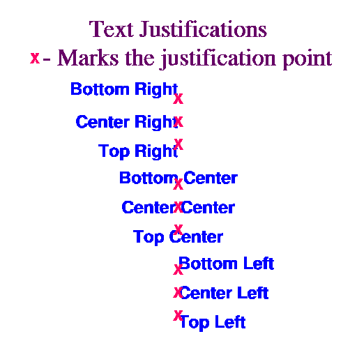
- vcExplicitLabelBarLabelsOn
-
This boolean resource allows you control the labels that appear in the
VectorPlot LabelBar explicitly. When
set True, VectorPlot does not block the
LabelBar resources
lbLabelStrings and
lbLabelAlignment. Therefore you can directly control both the
contents of the LabelBar's label strings and their
alignment with respect to the label boxes. When
vcExplicitLabelBarLabelsOn is set False,
VectorPlot sets both of these resources based on the
current vector line labels and the value of the resource
vcLabelBarEndLabelsOn. If you set this resource True but do
not set the
lbLabelStrings array resource,
VectorPlot will set it for you one time. This allows
you to get an initial set of strings as a starting point for any
customization you want to perform.
Default: False
- vcFillArrowEdgeColor
-
When vcMonoFillArrowEdgeColor is set True, this
resource of type NhlTColorIndex
sets a uniform color index for the edges of all filled vector arrows.
If set to
Transparent(-1), the edge line will not be drawn at all for filled vectors, assuming the fill color index is set to a value other thanTransparent. This resource has an effect only when vcGlyphStyle is set toFillArrow.Default:
Background - vcFillArrowEdgeThicknessF
-
This resource sets the thickness of the lines used to form the edges
of filled vector arrows. The value acts as a multiplier of a
(device-dependent) unit thickness. If vcFillOverEdge is set
True, note that the edge will not fully appear unless it is drawn
using thickness greater than 1.0. This resource has an effect only
when vcGlyphStyle is set to
FillArrow.Default: 2.0
- vcFillArrowFillColor
-
When vcMonoFillArrowFillColor is set True, this resource of
type
NhlTColorIndex
sets a uniform fill color index for all filled vector arrows. If set
to
Transparent(-1), the arrow will not be filled at all and only the perimeter will be drawn. This resource has an effect only when vcGlyphStyle is set toFillArrow.Default:
Foreground - vcFillArrowHeadInteriorXF
-
This resource specifies the distance from the point of the arrowhead
of a filled vector arrow drawn at the reference length to the point
where the arrowhead joins with the line extending to the tail of the
arrow. The value represents a fraction of the value of
vcRefLengthF. (See
figure.) This
distance is adjusted proportionally to the X component of the
arrowhead size for all vector arrows.
The value of vcFillArrowHeadInteriorXF is constrained to the
range 0.0 through 1.0. This resource has an effect only
when vcGlyphStyle is set to
FillArrow.Default: 0.33
- vcFillArrowHeadMinFracXF
-
This resource specifies the X component of the arrowhead size for a
filled arrow drawn at the minimum length, as a fraction of the
component length specified by vcFillArrowHeadXF. (See
figure.) If given the
value 1.0, the arrowhead X component will be the same for all arrows
in the plot, regardless of their length.
The value of vcFillArrowHeadMinFracXF is constrained to the
range 0.0 through 1.0. This resource has an effect only
when vcGlyphStyle is set to
FillArrow.Default: 0.25
- vcFillArrowHeadMinFracYF
-
This resource, when added to the minimum width value, specifies the Y
component length of the arrowhead size for a filled arrow drawn at the
minimum length, as a fraction of the component length specified by
vcFillArrowHeadYF. (See
figure.) If given the
value 1.0, the arrowhead Y component will extend the same distance
perpendicularly from the edge of all arrows in the plot, regardless of
their length and width. This can be a useful resource to adjust to
ensure that the points of even very short vector arrows remain
visible.
The value of vcFillArrowHeadMinFracYF is constrained to the
range 0.0 through 1.0. This resource has an effect only
when vcGlyphStyle is set to
FillArrow.Default: 0.25
- vcFillArrowHeadXF
-
This resource specifies the distance from the point of the arrowhead
of a filled vector arrow drawn at the reference length to its back
tips along the centerline of the arrow. The value represents a
fraction of the value of vcRefLengthF and determines the X
component of the arrowhead size. (See
figure.) If vcFillArrowHeadMinFracXF
has the value 0.0, then the ratio of the X component of the arrowhead size to
the arrow length will be invariant for all vectors in the plot.
The value of vcFillArrowHeadXF is constrained to the
range 0.0 through 2.0. This resource has an effect only
when vcGlyphStyle is set to
FillArrow.Default: 0.36
- vcFillArrowHeadYF
-
This resource specifies the perpendicular distance from one side of a
filled vector arrow drawn at the reference length to one of the back
tips of the arrowhead. The value represents a fraction of the value of
vcRefLengthF and, when added to half the arrow width,
determines the Y component of the arrowhead size. (See
figure.) If both
vcFillArrowHeadMinFracYF and vcFillArrowMinFracWidthF
have the value 0.0, then the ratio of the Y component of the arrowhead
size to the arrow length will be invariant for all vectors in the
plot.
The value of vcFillArrowHeadYF is constrained to the
range 0.0 through 1.0. This resource has an effect only
when vcGlyphStyle is set to
FillArrow.Default: 0.12
- vcFillArrowMinFracWidthF
-
This resource specifies the width of a filled arrow drawn at the
minimum length, as a fraction of the width specified by
vcFillArrowWidthF. (See
figure.) If given the
value 1.0, all arrows in the plot will be drawn at the same width,
regardless of their length.
The value of vcFillArrowMinFracWidthF is constrained to the
range 0.0 through 1.0. This resource has an effect only
when vcGlyphStyle is set to
FillArrow.Default: 0.25
- vcFillArrowWidthF
-
This resource specifies the width of a filled vector arrow drawn at
the reference length as a fraction of vcRefLengthF. (See
figure.) If
vcFillArrowMinFracWidthF has the value 0.0, then the ratio of
the arrow width to the arrow length will be invariant for all arrows
in the plot. The value of vcFillArrowWidthF is constrained to the
range 0.0 through 1.0. This resource has an effect only
when vcGlyphStyle is set to
FillArrow.Default: 0.1
- vcFillArrowsOn
-
vcGlyphStyle overrides and eventually is intended to replace
this resource. However, if you set vcFillArrowsOn and do not
at the same time set vcGlyphStyle, you can use it to select
between the
LineArrowandFillArrowglyph styles. When set True, fill arrows are selected; when set False, line arrows are selected.Default: False
- vcFillOverEdge
-
If this boolean resource is set True, the perimeter outline of a
filled vector arrow is drawn first, underneath the fill. In this case,
the line must be drawn using a line thickness greater than 1.0 in
order for the line to appear. The advantage of drawing the line
underneath is that the full extent of the fill appears; when the line
is drawn on top of the fill using a different color index, the fill
color may be partially or completely obscured, especially for small
vector arrows. This resource has an effect only when
vcGlyphStyle is set to
FillArrow.Default: True
- vcGlyphOpacityF
-
Available in version 6.1.0 and later.
Sets the opacity of vector glyphs in a plot. Specify a floating-point value between 0.0 (completely transparent) to 1.0 (fully opaque).
Default: 1.0
- vcGlyphStyle
-
This resource selects the style of glyph used to represent the vector
magnitude and direction. There are four choices:
LineArrow- Vectors are represented using an arrow-shaped polyline pointing in the direction of the vector. The arrow length and head size may vary with the magnitude of the vector. Resources prefixed by vcLineArrow... have an effect when vcGlyphStyle is set to this value.
FillArrow- Vectors are represented using a polygon and possibly a polyline edge that point in the direction of the vector. The length, width, and various parameters affecting the head size and overall shape may vary with the magnitude of the vector. Resources prefixed by vcFillArrow... have an effect when vcGlyphStyle is set to this value.
WindBarb- Vectors are represented using a standard wind barb glyph, composed of a shaft parallel to the vector direction, and pennants and/or ticks spaced at even intervals along the shaft starting at the end nearest the direction from which the flow is coming. (For the purposes of the vcPositionMode resource, this end is the "tail" of the wind barb.) If the velocity is less than 2.5 in magnitude, a circle is drawn instead of the barbed shaft. Otherwise half ticks represent 5 units of magnitude, full ticks represent 10 units, and pennants represent 50 units. By convention, the units usually represent knots. The pennants are drawn using a filled polygon, while the ticks, the shaft, and the calm circle are all rendered with polylines. Unlike the other glyph styles, wind barbs maintain a basically uniform length for all magnitudes. Resources prefixed by vcWindBarb... have an effect when vcGlyphStyle is set to this value.
CurlyVector- Vector are represented using a curved polyline tangent to the
instantaneous flow in the neighborhood of the grid point. A
variably-sized arrowhead at one end of the line points in the
direction of the flow. The path length of the curve may vary with the
vector magnitude at the grid point location.
CurlyVectormode is likeLineArrowmode in that it is rendered using a polyline, and therefore resources prefixed by vcLineArrow... have an effect when vcGlyphStyle is set to this value. Unlike the other glyph styles, when vectors drawn with this style are colored, the color varies along the path length of the vector depending on the interpolated value of the magnitude or other scalar field at each step along the path.
This resource overrides and eventually is intended to replace the resource vcFillArrowsOn. vcFillArrowsOn can still be used to choose between line arrows and fill arrows, as long as you do not set vcGlyphStyle at the same time.
Default:
LineArrow - vcLabelBarEndLabelsOn
-
When this boolean resource is set True and
vcExplicitLabelBarLabelsOn is False,
VectorPlot creates labels for the two ends of
the LabelBar. The label at one end will be a
string representation of a minimum value and at the other end
will be a string representation of the maximum value. These
values represent either a vector magnitude or, if
vcUseScalarArray is set True, some other scalar value.
Both strings will be formatted according to the format
specification in effect for the other labels provided by
VectorPlot to the LabelBar.
Default: False
- vcLabelFontColor
-
If vcLabelsUseVectorColor is set False, this resource
specifies the HLU color index used to draw the vector
magnitude labels.
Default:
Foreground - vcLabelFontHeightF
-
This resource specifies the NDC height of characters used for vector
magnitude labels. The label font height scales with changes to the
viewport width, unless you explicitly set vcLabelFontHeightF
during the same call.
Default: <dynamic>
- vcLabelsOn
-
If this resource is set True, VectorPlot will place
labels representing the vector magnitude next to each arrow in the
vector field plot. These labels are primarily intended as a debugging
aid, since in order to avoid excessive overlap, you must typically set
the label text size too small to be readable without
magnification. For this reason, only a few resources are available to
control the appearance of these labels. They are rendered using low
quality text.
Default: False
- vcLabelsUseVectorColor
-
If this resource is set True, VectorPlot draws
the vector magnitude labels using the color of the corresponding
vector. Otherwise the labels are drawn using the color index specified
by vcLabelFontColor.
Default: False
- vcLevelColors
-
The elements of this array of type NhlTColorIndexGenArray
can be set using an array of color indexes, an array of
named colors, or an array
of RGB
or RGBA values.
If vcGlyphStyle is set to
LineArroworCurlyVectorand vcMonoLineArrowColor is False, this resource controls the color of the line-drawn vector arrows. If vcGlyphStyle is set toFillArrow, then this resource may control the fill and/or the edge color of the filled vector arrows, depending on the values of the resources vcMonoFillArrowFillColor and vcMonoFillArrowEdgeColor. If vcGlyphStyle is set toWindBarband vcMonoWindBarbColor is False, this resource controls the color of the wind barb glyphs.Each element of vcLevelColors specifies a color for vectors whose associated scalar data value is less than the corresponding element of the vcLevels array. Note that there is always one more color than there are vector levels. The first element of vcLevelColors specifies a color index for any vector with an associated data value less than the value of vcMinLevelValF. The highest currently used element of vcLevelColors specifies a color for vectors with associated data values greater than the value of vcMaxLevelValF.
When vcGlyphStyle is set to
CurlyVector, the vectors appear multicolored with the color varying along the path length of the vector depending on the interpolated value of the magnitude or other scalar field at each incremental step.Although backwards compatibility is for the most part maintained, beginning with version 6.1.0, this resource supports the new 32-bit color model, as follows:
If vcLevelColors is not set explicitly, its values are derived from the settings of vcLevelPalette and vcSpanLevelPalette, or, if vcLevelPalette is not set, wkColorMap and vcSpanLevelPalette. If vcSpanLevelPalette is
True, the values are distributed evenly through the range of colors available from vcLevelPalette or wkColorMap. Otherwise, the values are sequential. If the color indexes are derived from vcLevelPalette the first color comes from element 0, whereas if they are derived from wkColorMap, the first color comes from element 2. This is because wkColorMap contains special elements (0 and 1) for theBackgroundandForegroundcolors, whereas the palette-type resources do not. If some but not all of the available elements of vcLevelColors are explicitly set, the remaining elements will be determined as if vcSpanLevelPalette has the valueFalse.For backwards compatibility, colors set based on wkColorMap remain indexed to the current color map associated with the workstation. Consequently, if the workstation color map is changed prior to drawing the plot, the color indexes will map into the new color map. In contrast, color indexes derived from the vcLevelPalette resource always refer to a specific color regardless of changes to wkColorMap.
Default: <dynamic>
- vcLevelCount
-
A read-only resource set to the actual number of levels chosen during
the level selection process.
Default: 16
- vcLevelPalette
-
Available in version 6.1.0 and later.
This resource of type NhlTColorDefinitionGenArray allows you to set a color palette from which the values assigned to vcLevelColors are chosen.
You can set this resource to the string name of a predefined color map, an array of named colors, or an array of RGB or RGBA values. If you set vcLevelPalette using a predefined color map, it will have two fewer elements than if you set wkColorMap using the same color map. This is because the wkColorMap resource contains special elements (0 and 1) for the
BackgroundandForegroundcolors, whereas the palette-type resources do not. Use vcSpanLevelPalette to indicate whether to span the full color palette or to simply use sequentially increasing values.Default:
None - vcLevelSelectionMode
-
This enumerated resource of type NhlTLevelSelectionMode provides four
methods for selecting the levels used to color the vector arrows:
AutomaticLevels- Ordinarily this mode determines vector levels by picking a
spacing value from a set of relatively "round" numbers scaled by
powers of 10 to the range of the data. This set of numbers is as
follows: 1.0, 2.0, 2.5, 4.0, 5.0. The number of levels chosen will be
as close as possible to the value of vcMaxLevelCount without
exceeding it. Once the spacing is chosen, the minimum vector level is
set to the value of the least multiple of the spacing greater than the
minimum data value. Likewise the maximum vector level becomes the
greatest multiple of the spacing less than the maximum data value.
Based on these values, VectorPlot sets the resources
vcLevelSpacingF, vcMinLevelValF, and
vcMaxLevelValF appropriately.
On the other hand, if you explicitly set the resource vcLevelSpacingF to a valid value greater than 0.0 and less than the range of the data, it will be used as the interval spacing. The minimum and maximum levels are calculated as before. If as a consequence, vcMaxLevelCount is less than the number of levels so specified, it will be set to the number of levels actually needed. However, if the choice of spacing causes the absolute maximum number of levels (currently 255) to be exceeded, VectorPlot will issue a warning message and recalculate the spacing as previously described.
In any case, VectorPlot sets the elements of the array resource vcLevels to the values of the vector levels chosen and the read-only resource vcLevelCount to the number of levels.
ManualLevelsManualLevelsmode bases the choice of vector levels on the values of the resources vcLevelSpacingF, vcMinLevelValF, and vcMaxLevelValF. Starting at vcMinLevelValF, vector levels are created at intervals spaced by the value of vcLevelSpacingF until vcMaxLevelValF is reached. The final vector level will always be vcMaxLevelValF. VectorPlot sets elements of the array resource vcLevels to the values of each vector level chosen and the read-only resource vcLevelCount to the number of levels. If the current value of vcMaxLevelCount is less than vcLevelCount, it is reset to the value of vcLevelCount. However, if the level count would exceed the absolute maximum number of levels, currently 255, VectorPlot issues a warning and chooses a new value of vcLevelSpacingF based on the value of vcMaxLevelCount.If you choose
ManualLevelsselection mode when the VectorPlot object is created, and do not set vcMinLevelValF, VectorPlot will choose levels as if you had setAutomaticLevelsmode. If you set vcMinLevelValF only, a default spacing is used, and the value of vcMaxLevelValF is determined as it would be forAutomaticLevelsmode.ExplicitLevels- This mode allows you to specify the value of each vector
level by explicitly setting the contents of the vcLevels
array. If you choose
ExplicitLevelsselection mode when creating a VectorPlot object, but do not specify the contents of the vcLevels array, VectorPlot will choose levels as if you had specifiedAutomaticLevelsmode. Thereafter, when you setExplicitLevelsmode, VectorPlot uses the current contents of vcLevels, whether or not you set it explicitly.If the number of elements in vcLevels exceeds the absolute maximum number of levels (currently 255), VectorPlot issues a warning and the mode defaults to
AutomaticLevels. Note that VectorPlot always sorts the elements of vcLevels into a monotonically increasing sequence. After sorting, vcMinLevelValF is set equal to the value of first element of vcLevels, and vcMaxLevelValF is set to the value of the last element. vcLevelSpacingF is set to the average value of the spacing separating each level. EqualSpacedLevels- For this mode, VectorPlot divides the range spanning the dataset minimum and maximum values into vcMaxLevelCount+1 equally spaced intervals. vcLevelSpacingF is set to the value of this interval. vcMinLevelValF is set to the value of the dataset minimum plus the value of vcLevelSpacingF. vcMaxLevelValF is set to the value of the dataset maximum minus the value of vcLevelSpacingF. This results in vcMaxLevelCount levels; therefore VectorPlot sets the read-only resource vcLevelCount equal to vcMaxLevelCount.
Default:
AutomaticLevels - vcLevelSpacingF
-
When the vcLevelSelectionMode is
ManualLevelsor when the vcLevelSelectionMode isAutomaticLevels, and vcLevelSpacingF is explicitly set, vcLevelSpacingF determines the spacing between vector intervals. Otherwise, the VectorPlot object sets the value of vcLevelSpacingF based on the vector levels actually chosen. When the vcLevelSelectionMode isExplicitLevels, vcLevelSpacingF will be set to the arithmetic average of the spacing between levels.Default: 5.0
- vcLevels
-
An array of floats containing values that determine the color of
the vector arrows in the vector field plot. If
vcScalarFieldData is valid and the resource
vcUseScalarArray is set True, the level values are
based on the scalar array data; otherwise the level values are
based on the magnitudes of the vector elements in the vector
field. If the vcLevelSelectionMode is
ExplicitLevels, you may set these values yourself. Otherwise, the VectorPlot object sets the elements of this array.Default: <dynamic>
- vcLineArrowColor
-
When vcMonoLineArrowColor is set True, this resource
of type NhlTColorIndex sets a
uniform color index for all lines used to draw vector arrows. If set
to
Transparent(-1), the line color index will be constrained to the valueForeground(1). This resource has an effect only when vcGlyphStyle is set toLineArroworCurlyVector.Default:
Foreground - vcLineArrowHeadMaxSizeF
-
Specifies a maximum length for the lines that form the point of the
arrowhead of line-drawn vectors, as a fraction of the viewport width.
Normally the arrowhead size is scaled proportionally to the length of
the vector. This resource allows you to ensure that the arrowheads do
not become excessively large for high magnitude vectors. If
vcLineArrowHeadMinSizeF is set to the same value as
vcLineArrowHeadMaxSizeF, all arrowheads in the vector plot will
be drawn at the same size. Setting both resources to 0.0 will cause
the arrows to be drawn without any heads at all. This resource has an
effect only when vcGlyphStyle is set to
LineArroworCurlyVector.Default: 0.05 (
LineArrow), 0.012 (CurlyVector) - vcLineArrowHeadMinSizeF
-
Specifies a minimum length for the lines that form the point of the
arrowhead of line-drawn vectors, as a fraction of the viewport
width. Normally the arrowhead size is scaled proportionally to the
length of the vector. This resource allows you to ensure that the
arrowhead will remain recognizable even for very short vectors. If
vcLineArrowHeadMinSizeF is set to the same value as
vcLineArrowHeadMaxSizeF, all arrowheads in the vector plot will
be drawn at the same size. Setting both resources to 0.0 will cause
the arrows to be drawn without any heads at all. This resource has an
effect only when vcGlyphStyle is set to
LineArroworCurlyVector.Default: 0.005
- vcLineArrowThicknessF
-
This resource sets the thickness of the line used to draw vector line
arrows. The value acts as a multiplier of a (device-dependent) unit
thickness. This resource has an effect only when vcGlyphStyle
is set to
LineArroworCurlyVector.Default: 1.0
- vcMagnitudeFormat
-
The vcMagnitudeFormat resource is a string that specifies
the printing format for vector field values according to the HLU
Floating Point Format Specification
scheme. This resource controls the formatting of any
number representing VectorField data when used in a
VectorPlot annotation.
Default: "*+^sg"
- vcMagnitudeScaleFactorF
-
vcMagnitudeScaleFactorF is a read-only resource that contains
the current scale factor that applies to annotations with numbers
representing magnitudes in the VectorField data
object. Multiplying the numbers in the annotations by the value of
vcMagnitudeScaleFactorF gives the actual magnitudes the
numbers represent. VectorPlot
calculates its value based on the maximum vector magnitude, the
current mode of the enumerated resource,
vcMagnitudeScalingMode, and perhaps the value of
vcMagnitudeScaleValueF. Its value may also be influenced by
the number of significant digits specified by the format specification
resource, vcMagnitudeFormat.
Default: 1.0
- vcMagnitudeScaleValueF
-
The interpretation of vcMagnitudeScaleValueF depends on the
value of the enumerated resource vcMagnitudeScalingMode. When
vcMagnitudeScalingMode is set to
ScaleFactor, values are divided by the value of vcMagnitudeScaleValueF to obtain the numbers appearing in VectorPlot object labels. If vcMagnitudeScalingMode is set toConfineToRange, the vcMagnitudeScaleValueF represents an exclusive upper bound for the numbers used to represent the data values. For other values of vcMagnitudeScalingMode, the vcMagnitudeScaleValueF resource is ignored.Default: 1.0
- vcMagnitudeScalingMode
-
This resource of type NhlTScalingMode determines how numbers
representing magnitudes in the vector field data are scaled when they
appear in the annotations provided by VectorPlot.
There are five choices:
ScaleFactor- The VectorPlot object divides the magnitude by the value of vcMagnitudeScaleValueF to obtain the number that appears in the label.
ConfineToRange- The VectorPlot object uses vcMagnitudeScaleValueF as an exclusive upper bound. A scale factor is selected such that the scaled maximum magnitude will be less than vcMagnitudeScaleValueF, but greater than or equal to vcMagnitudeScaleValueF divided by 10.0. As an example, setting vcMagnitudeScaleValueF to 100.0 would result in the number used to represent the scaled maximum magnitude falling in the range 10.0 to 99.999....
TrimZeros- The VectorPlot object selects a scale factor such that the number representing the scaled maximum magnitude will have the fewest possible extra zeros. If the maximum magnitude were 245000, for instance, it would scale to 245. If it were 0.000245, it would scale to 0.245. (The zero conventionally placed before the decimal point of a number less than 1.0 is not considered.)
MaxSigDigitsLeft- The VectorPlot object selects a scale factor such that the number representing the scaled maximum magnitude will have its rightmost significant digit directly to the left of the decimal point. The number of significant digits is determined by the format string resource, vcMagnitudeFormat.
AllIntegers- The VectorPlot object selects a scale factor such that the numbers representing the vector levels (as determined by examination of the values of the vcLevels array) are reduced to integers.
Default:
ScaleFactor - vcMapDirection
-
This resource controls whether the vector direction is mapped
into the same coordinate space as the vector location, or whether
it is rendered in a locally uniform cartesian coordinate
space. This resource has an effect whenever a non-uniform
transformation is in effect. These include most of the
MapTransformation transformations and
IrregularTransformation transformations. Also included
are logarithmic transformations provided by the
LogLinTransformation and even linear transformations when
the X and Y unit sizes are different.
Default: True
- vcMaxLevelCount
-
When the vcLevelSelectionMode is
AutomaticLevelsand vcLevelSpacingF is not explicitly set, VectorPlot picks a number of levels less than or equal to the current value of vcMaxLevelCount. If the vcLevelSelectionMode isEqualSpacedLevels, VectorPlot picks exactly vcMaxLevelCount levels. If vcMaxLevelCount exceeds the absolute maximum level count allowed by VectorPlot (currently 255), a warning is issued and the value is reset to this maximum. If vcLevelSelectionMode isManualLevelsorExplicitLevelsorAutomaticLevelswith vcLevelSpacingF explicitly set, VectorPlot sets vcMaxLevelCount to the number of levels actually used if this number is greater than the current value of vcMaxLevelCount.Default: 16
- vcMaxLevelValF
-
When the vcLevelSelectionMode is
ManualLevels, the value of vcMaxLevelValF, if set, determines the highest vector level. Otherwise, VectorPlot sets the vcMaxLevelValF to a value equal to highest vector level picked.Default: <dynamic>
- vcMaxMagnitudeF
-
This resource specifies a maximum magnitude for elements of the
vector field. Vectors with magnitudes greater than this value will not
be rendered in the vector field plot.
Default: 0.0
- vcMinAnnoAngleF
-
NOT YET IMPLEMENTED.
Default: 0.0
- vcMinAnnoArrowAngleF
-
This resource specifies the angle, in degrees, of the arrow used in
the minimum vector annotation.
Default: 0.0
- vcMinAnnoArrowEdgeColor
-
If vcMinAnnoArrowUseVecColor is set False, this resource
specifies the HLU line color index used to render the arrow in the
reference annotation. If vcMinAnnoArrowUseVecColor is set
True, and either vcUseScalarArray or
vcMonoLineArrowColor is True, the line color index is determined
from the value of vcLineArrowColor. If
vcMinAnnoArrowUseVecColor is set True otherwise, the line color
index is determined based on the magnitude of the reference annotation
vector and the vcLevelColors array resource.
Default:
Foreground - vcMinAnnoArrowFillColor
-
If vcMinAnnoArrowUseVecColor is set False, this resource
specifies the HLU fill color index used to render the arrow in the
reference annotation. If vcMinAnnoArrowUseVecColor is set
True, and either vcUseScalarArray or
vcMonoFillArrowFillColor is True, the fill color index is
determined from the value of vcFillArrowFillColor. If
vcMinAnnoArrowUseVecColor is set True otherwise, the fill
color index is determined based on the magnitude of the reference
annotation vector and the vcLevelColors array resource. This
resource has an effect only when vcGlyphStyle is set to
FillArrow.Default:
Foreground - vcMinAnnoArrowLineColor
-
If vcMinAnnoArrowUseVecColor is set False, this resource
specifies the HLU line color index used to render the arrow in the
reference annotation. If vcMinAnnoArrowUseVecColor is set
True, and either vcUseScalarArray or
vcMonoLineArrowColor is True, the line color index is determined
from the value of vcLineArrowColor. If
vcMinAnnoArrowUseVecColor is set True otherwise, the line color
index is determined based on the magnitude of the reference annotation
vector and the vcLevelColors array resource.
Default:
Foreground - vcMinAnnoArrowMinOffsetF
-
This resource specifies the minimum amount of space between the
minimum vector annotation arrow and the text on either side
in units of the minimum annotation font height.
Default: 0.25
- vcMinAnnoArrowSpaceF
-
This resource specifies the minimum amount of space reserved for the
reference vector annotation arrow in units of the minimum annotation
font height. More space may be used if the arrow extent (in units of
the font height) plus twice the value of vcMinAnnoArrowMinOffsetF
exceeds this value.
Default: 2.0
- vcMinAnnoArrowUseVecColor
-
If this resource is set True, VectorPlot will base
the coloring of the minimum arrow on the colors used to draw the
vector plot arrows as follows: if coloring by magnitude is in effect
(vcUseScalarArray and, depending on the value of vcGlyphStyle,
the appropriate "mono" color flag is set False),
then the color will be that assigned to vectors representing
the magnitude of the minimum annotation vector; otherwise, the color
index will be determined from the current values assigned to
vcLineArrowColor and/or vcFillArrowFillColor. If
vcMinAnnoArrowUseVecColor is False, then
vcMinAnnoArrowLineColor and vcMinAnnoArrowFillColor control
the color of the minimum annotation arrow.
Default: True
- vcMinAnnoBackgroundColor
-
This resource sets the background color used to fill the box surrounding
the vector minimum annotation. If you do not want the box to be
filled at all, set vcMinAnnoBackgroundColor
to
Transparent(-1).Default:
Background - vcMinAnnoConstantSpacingF
-
Normally when vcMinAnnoFontQuality is set to
High, VectorPlot draws the minimum vector annotation text using proportional spacing. Setting the vcMinAnnoConstantSpacingF to a value greater than 0.0 overrides this behavior. Instead, the distance from the start of one character to the next is computed by multiplying a single standard character width by the value of vcMinAnnoConstantSpacingF. When vcMinAnnoConstantSpacingF has a value between 0.0 and 1.0, characters will overlap. A value of 1.0 implies, on average, no space between characters, while values increasing from 1.0 cause the space between characters to grow. This parameter is ignored when vcMinAnnoFontQuality is notHigh. Values less than 0.0 result in an error and are replaced with the default value.Default: 0.0
- vcMinAnnoExplicitMagnitudeF
-
By default, the arrow in the minimum vector annotation is drawn
at the size of the current VectorPlot minimum
magnitude. However, if you set this resource to a value greater than
its default value of 0.0, the size of arrow will reflect the
vector magnitude represented by this value.
Default: 0.0
- vcMinAnnoFont
-
This resource of type NhlTFont
specifies the font used to render the vector minimum annotation.
Default: "pwritx"
- vcMinAnnoFontAspectF
-
This resource determines the shape of the minimum vector annotation
characters. Values increasing from 1.0 result in
characters that appear thinner. Values decreasing from 1.0
make the characters appear wider. Values less than or equal to 0.0
result in a WARNING message and a restoration of the default value.
Default: 1.3125
- vcMinAnnoFontColor
-
This resource specifies the HLU color index used to render
vector minimum annotation text.
Default:
Foreground - vcMinAnnoFontHeightF
-
This resource controls the height, in
NDC units, of characters
used in the text of the minimum vector annotation. The character width
scales proportionally, unless you also modify the aspect ratio using the
vcMinAnnoFontAspectF resource. The minimum annotation
font height scales with changes to the viewport width,
unless you explicitly set vcMinAnnoFontHeightF during
the same call.
Default: <dynamic>
- vcMinAnnoFontQuality
-
This resource of type NhlTFontQuality determines the quality of
the font used to draw the VectorPlot vector
minimum annotation.
Default:
High - vcMinAnnoFontThicknessF
-
Sets the thickness of the line used to draw vector minimum annotation
text. The value acts as a multiplier of a (device-dependent) unit
thickness. This resource is ignored when the vcMinAnnoFont
specifies a filled font (font indexes 21-22, 25-26, 29-30, and 33-37).
Default: 1.0
- vcMinAnnoFuncCode
-
This resource of type NhlTCharacter
sets the function code
character for the minimum vector annotation strings.
Note: the default function code was a colon (:) in NCL Versions 6.0.0 and earlier.
Default: ~
- vcMinAnnoJust
-
This resource of type NhlTJustification, after constraint to an
appropriate value based on vcMinAnnoSide, sets the
justification of the vector minimum annotation with respect to its
base location. The PlotManager
Location Control Model requires this resource to allow
control of the vector minimum annotation consistent with other
annotations.
Default:
TopRight - vcMinAnnoOn
-
If this boolean resource is set False, VectorPlot
will not draw the minimum vector annotation.
Default: True
- vcMinAnnoOrientation
-
NOT YET IMPLEMENTED
This resource of type NhlTOrientation specifies whether the elements of the minimum vector annotation (two strings with an arrow representing a vector magnitude in between) are stacked vertically or placed side by side horizontally.
Default:
Vertical - vcMinAnnoOrthogonalPosF
-
vcMinAnnoOrthogonalPosF sets the coordinate of the base
location of the vector minimum annotation
orthogonal to the current vcMinAnnoSide and directed away
from the center of the viewport. The
PlotManager Location Control Model requires this resource to allow control of the
vector minimum annotation consistent with other annotations.
Default: 0.02
- vcMinAnnoParallelPosF
-
vcMinAnnoParallelPosF specifies the coordinate of the base
location of the vector minimum annotation
parallel to the current vcMinAnnoSide and directed toward
increasing NDC values. The
PlotManager Location Control Model requires this resource to allow control of the
vector minimum annotation consistent with other annotations.
Default: 1.0
- vcMinAnnoPerimColor
-
This resource sets the HLU color index used to draw the perimeter of
the vector minimum annotation.
Default:
Foreground - vcMinAnnoPerimOn
-
vcMinAnnoPerimOn is a boolean resource that determines
whether VectorPlot will draw an outline around the
perimeter of the box surrounding the minimum vector annotation.
If set False, no outline will be drawn.
Default: True
- vcMinAnnoPerimSpaceF
-
vcMinAnnoPerimSpaceF determines the spacing, or margin,
between the text of the minimum vector annotation and its edge
as a fraction of current minimum annotation font height.
Default: 0.33
- vcMinAnnoPerimThicknessF
-
This resource determines the thickness of the perimeter line around
the vector minimum annotation. The value acts as a multiplier of a
(device-dependent) unit thickness.
Default: 1.0
- vcMinAnnoSide
-
This resource of type NhlTPosition
determines where to place the vector minimum annotation in relation to
the sides of the plot object. The PlotManager
Location Control Model requires this resource to allow
control of the vector minimum annotation consistent with other
annotations. Its value determines a coordinate system origin and the
direction of the positional resources
vcMinAnnoParallelPosF and
vcMinAnnoOrthogonalPosF. It also constrains the
value of vcMinAnnoJust appropriately. There are four
settings, which behave as follows, unless
vcMinAnnoZone is set to one of the special zones (0
or 1):
Top- The PlotManager locates the vector minimum
annotation relative to a line paralleling the top viewport boundary.
vcMinAnnoOrthogonalPosF increases in the direction of
increasing NDC Y-Axis values and is constrained to positive values.
vcMinAnnoParallelPosF increases in the direction of
increasing NDC X-Axis values. vcMinAnnoJust is constrained
to
BottomRight,BottomCenter, orBottomLeft. Bottom- The PlotManager locates the vector minimum
annotation relative to a line paralleling the bottom
viewport boundary. vcMinAnnoOrthogonalPosF increases in
the direction of decreasing NDC Y-Axis values and is constrained to
positive values. vcMinAnnoParallelPosF increases in the
direction of increasing NDC X-Axis values. vcMinAnnoJust is
constrained to
TopRight,TopCenter, orTopLeft. Right- The PlotManager locates the vector minimum
annotation relative to a line paralleling the right viewport
boundary. vcMinAnnoOrthogonalPosF increases in the
direction of increasing NDC X-Axis values and is constrained to
positive values. vcMinAnnoParallelPosF increases in the
direction of increasing NDC Y-Axis values. vcMinAnnoJust is
constrained to
TopLeft,CenterLeft, orBottomLeft. Left- The PlotManager locates the vector minimum
annotation relative to a line paralleling the left viewport boundary.
vcMinAnnoOrthogonalPosF increases in the direction of
decreasing NDC X-Axis values and is constrained to positive values.
vcMinAnnoParallelPosF increases in the direction of
increasing NDC Y-Axis values. vcMinAnnoJust is constrained
to
TopRight,CenterRight, orBottomRight.
Default:
Bottom - vcMinAnnoString1
-
Specifies the string to use above or to the left (depending on the
current value of vcMinAnnoOrientation) of the arrow
in the minimum vector annotation. The string may contain function codes
and/or substitution
substrings.
vcMagnitudeFormat determines the format of all numbers related to the vector field, and all numbers, except for the number generated from the substitution substring $MSF$, are scaled by the value of vcMagnitudeScaleFactorF. vcScalarValueFormat determines the format of all numbers related to the scalar field, and all numbers, except for the number generated from the substitution substring $SSF$, are scaled by the value of vcScalarValueScaleFactorF.
Default: "$VMG$"
- vcMinAnnoString1On
-
If this boolean resource is set False,
VectorPlot will not display a string above or to
the left (depending on the current value of
vcMinAnnoOrientation) of the minimum annotation
arrow. Otherwise, the string will be displayed.
Default: True
- vcMinAnnoString2
-
Specifies the string to use above or to the left (depending on
the current value of vcMinAnnoOrientation) of the arrow
in the minimum vector annotation.
The string may contain function codes
and/or substitution
substrings.
vcMagnitudeFormat determines the format of all numbers related to the vector field, and all numbers, except for the number generated from the substitution substring $MSF$, are scaled by the value of vcMagnitudeScaleFactorF. vcScalarValueFormat determines the format of all numbers related to the scalar field, and all numbers, except for the number generated from the substitution substring $SSF$, are scaled by the value of vcScalarValueScaleFactorF.
Default: "Minimum Vector"
- vcMinAnnoString2On
-
If this boolean resource is set False,
VectorPlot will not display a string below or to
the right (depending on the current value of
vcMinAnnoOrientation) of the minimum annotation
arrow. Otherwise, the string will be displayed.
Default: True
- vcMinAnnoTextDirection
-
This resource of type NhlTTextDirection specifies the direction
of the text in the minimum vector annotation. There are two choices:
Down- Each character is placed below the previous character in the text string.
Across- Each character is placed to the right of the previous character in the text string.
Default:
Across - vcMinAnnoZone
-
VectorPlot implements the vector minimum annotation
as an embedded annotation. vcMinAnnoZone
specifies the PlotManager zone assigned to the
vector minimum annotation. The
PlotManager Location Control Model requires this resource to allow control of
the minimum annotation consistent with other annotations. If
vcMinAnnoZone is set to 0, the positional origin is the
center of the plot viewport; otherwise it is on or outside one of the
sides of the viewport.
Default: 3
- vcMinDistanceF
-
This resource specifies a minimum distance in NDC space that is to
separate the data locations of neighboring vectors. Vectors are
elimininated from the plot until there are no vectors closer than the
specified distance. Note that if the realized length of a vector
glyph is long enough, it is still possible that it may overlap
neighboring glyphs. However, the grid point locations are guaranteed
to be no closer than the distance specified. When this resource has
its default value, 0.0, the thinning algorithm is not applied.
Default: 0.0
- vcMinFracLengthF
-
If vcGlyphStyle is not set to
WindBarb, this resource specifies, as a fraction of the reference length (vcRefLengthF), the length used to render the minimum magnitude vector. If vcMinMagnitudeF is greater than 0.0, its value is used as the minimum magnitude; otherwise the magnitude of the smallest vector appearing in the plot is used as the minimum magnitude. The lengths of the remaining vectors are determined by scaling proportionally between this length and the reference length. Setting vcMinFracLengthF to the value 1.0 causes all vectors to be drawn with the same length. If vcMinFracLengthF has its default value, 0.0, the vector length is strictly proportional to its magnitude.If vcGlyphStyle is set to
WindBarb, the value of vcMinFracLengthF is effectively forced to the value 1.0, and its set value is ignored.Default: 0.0
- vcMinLevelValF
-
When the vcLevelSelectionMode is
ManualLevels, the value of vcMinLevelValF, if set, determines the lowest vector level. Otherwise, VectorPlot sets the vcMinLevelValF to a value equal to lowest vector level picked.Default: <dynamic>
- vcMinMagnitudeF
-
This resource specifies a minimum magnitude for elements of the
vector field. Vectors with magnitudes less than this value will not
be rendered in the vector field plot.
Default: 0.0
- vcMonoFillArrowEdgeColor
-
When set True, the edge color for all filled vector arrows is set to a
single HLU color index, as specified by the value of the scalar
resource vcFillArrowEdgeColor. When False, the elements of the
array resource vcLevelColors specify the edge color of each
arrow based on the scalar quantity associated with
the vector. This resource has an effect only when vcGlyphStyle is
set to
FillArrow.Default: True
- vcMonoFillArrowFillColor
-
When set True, the fill color for all filled vector arrows is set to a
single HLU color index, as specified by the value of the scalar
resource vcFillArrowFillColor. When False, the elements of
the array resource vcLevelColors specify the fill color of
each arrow based on the scalar quantity associated with the
vector. This resource has an effect only when vcGlyphStyle is
set to
FillArrow.Default: True
- vcMonoLineArrowColor
-
When this resource is set True, line-drawn vector arrows are colored
using a single HLU color index, as specified by the value of the
scalar resource vcLineArrowColor. When False, the elements of
the array resource vcLevelColors are used to set the color of
each vector line individually based on the scalar quantity associated
with the vector. This resource has an effect only when
vcGlyphStyle is set to
LineArroworCurlyVector.Default: True
- vcMonoWindBarbColor
-
When this resource is set True, wind barb glyphs are colored using a
single HLU color index, as specified by the value of the scalar
resource vcWindBarbColor. When False, the elements of the
array resource vcLevelColors are used to set the color of
each wind barb glyph individually based on the scalar quantity associated
with the vector. This resource has an effect only when
vcGlyphStyle is set to
WindBarb.Default: True
- vcNoDataLabelOn
-
This boolean resource, when set True, causes a label to appear when
a vectorplot is drawn without any data having been
provided. Except for the label string, all attributes of this label,
including its position, are set using resources belonging to the
constant field label. When set False, no such label appears.
Default: True
- vcNoDataLabelString
-
This resource contains the string that appears in the 'No Data' label
if you draw a VectorPlot object without providing
any data. No substitution substrings are allowed in this label, since
all the substitutions depend on data being available. Except for the
boolean switch that turns it on and off, all attributes of this label,
including its position, are set using resources belonging to the
constant field label.
Default: "NO VECTOR DATA"
- vcPositionMode
-
This resource of type NhlTVectorPositionMode specifies how the
vector arrow is positioned in the vector field plot relative to the
actual data location. There are three possibilites:
ArrowHead- The head of the arrow is placed at the data location.
ArrowCenter- The center of the arrow is placed at the data location.
ArrowTail- The tail of the arrow is placed at the data location.
Default:
ArrowCenter - vcRefAnnoAngleF
-
NOT YET IMPLEMENTED.
Default: 0.0
- vcRefAnnoArrowAngleF
-
This resource specifies the angle, in degrees, of the arrow used in
the reference vector annotation.
Default: 0.0
- vcRefAnnoArrowEdgeColor
-
If vcRefAnnoArrowUseVecColor is set False, this resource
specifies the HLU line color index used to render the arrow in the
reference annotation. If vcRefAnnoArrowUseVecColor is set
True, and either vcUseScalarArray or
vcMonoLineArrowColor is True, the line color index is determined
from the value of vcLineArrowColor. If
vcRefAnnoArrowUseVecColor is set True otherwise, the line color
index is determined based on the magnitude of the reference annotation
vector and the vcLevelColors array resource.
Default:
Foreground - vcRefAnnoArrowFillColor
-
If vcRefAnnoArrowUseVecColor is set False, this resource
specifies the HLU fill color index used to render the arrow in the
reference annotation. If vcRefAnnoArrowUseVecColor is set
True, and either vcUseScalarArray or
vcMonoFillArrowFillColor is True, the fill color index is
determined from the value of vcFillArrowFillColor. If
vcRefAnnoArrowUseVecColor is set True otherwise, the fill
color index is determined based on the magnitude of the reference
annotation vector and the vcLevelColors array resource. This
resource has an effect only when vcGlyphStyle is set to
FillArrow.Default:
Foreground - vcRefAnnoArrowLineColor
-
If vcRefAnnoArrowUseVecColor is set False, this resource
specifies the HLU line color index used to render the arrow in the
reference annotation. If vcRefAnnoArrowUseVecColor is set
True, and either vcUseScalarArray or
vcMonoLineArrowColor is True, the line color index is determined
from the value of vcLineArrowColor. If
vcRefAnnoArrowUseVecColor is set True otherwise, the line color
index is determined based on the magnitude of the reference annotation
vector and the vcLevelColors array resource.
Default:
Foreground - vcRefAnnoArrowMinOffsetF
-
This resource specifies the minimum amount of space between the
reference vector annotation arrow and the text on either side
in units of the reference annotation font height.
Default: 0.25
- vcRefAnnoArrowSpaceF
-
This resource specifies the minimum amount of space reserved for the
reference vector annotation arrow in units of the reference annotation
font height. More space may be used if the arrow extent (in units of
the font height) plus twice the value of
vcRefAnnoArrowMinOffsetF exceeds this value.
Default: 2.0
- vcRefAnnoArrowUseVecColor
-
If this resource is set True, VectorPlot will base
the coloring of the reference arrow on the colors used to draw the
vector plot arrows as follows: if coloring by magnitude is in effect
(vcUseScalarArray and and, depending on the value of vcGlyphStyle,
the appropriate "mono" color flag is set False),
then the color will be that assigned to vectors representing
the magnitude of the reference annotation vector; otherwise, the color
will be determined from the current values assigned to
vcLineArrowColor and/or vcFillArrowFillColor. If
vcRefAnnoArrowUseVecColor is False, then
vcRefAnnoArrowLineColor and vcRefAnnoArrowFillColor control
the color of the reference annotation arrow.
Default: True
- vcRefAnnoBackgroundColor
-
This resource sets the background color used to fill the box surrounding
the vector reference annotation. If you do not want the box to be
filled at all, set vcRefAnnoBackgroundColor
to
Transparent(-1).Default:
Background - vcRefAnnoConstantSpacingF
-
Normally when vcRefAnnoFontQuality is set to
High, VectorPlot draws the reference vector annotation text using proportional spacing. Setting the vcRefAnnoConstantSpacingF to a value greater than 0.0 overrides this behavior. Instead, the distance from the start of one character to the next is computed by multiplying a single standard character width by the value of vcRefAnnoConstantSpacingF. When vcRefAnnoConstantSpacingF has a value between 0.0 and 1.0, characters will overlap. A value of 1.0 implies, on average, no space between characters, while values increasing from 1.0 cause the space between characters to grow. This parameter is ignored when vcRefAnnoFontQuality is notHigh. Values less than 0.0 result in an error and are replaced with the default value.Default: 0.0
- vcRefAnnoExplicitMagnitudeF
-
By default, the arrow in the reference vector annotation is drawn
at the size of the current VectorPlot reference
magnitude. However, if you set this resource to a value greater than
its default value of 0.0, the size of the arrow will reflect the
vector magnitude represented by this value.
Default: 0.0
- vcRefAnnoFont
-
This resource of type NhlTFont
specifies the font used to render the vector reference annotation.
Default: "pwritx"
- vcRefAnnoFontAspectF
-
This resource determines the shape of the reference vector annotation
characters. Values increasing from 1.0 result in
characters that appear thinner. Values decreasing from 1.0
make the characters appear wider. Values less than or equal to 0.0
result in a WARNING message and a restoration of the default value.
Default: 1.3125
- vcRefAnnoFontColor
-
This resource specifies the HLU color index used to render
vector reference annotation text.
Default:
Foreground - vcRefAnnoFontHeightF
-
This resource controls the height, in
NDC units, of characters
used in the text of the reference vector annotation. The character width
scales proportionally, unless you also modify the aspect ratio using the
vcRefAnnoFontAspectF resource. The reference annotation font
height scales with changes to the viewport width, unless you explicitly
set vcRefAnnoFontHeightF during the same call.
Default: <dynamic>
- vcRefAnnoFontQuality
-
This resource of type NhlTFontQuality determines the quality of
the font used to draw the VectorPlot vector
reference annotation.
Default:
High - vcRefAnnoFontThicknessF
-
Sets the thickness of the line used to draw vector reference annotation
text. The value acts as a multiplier of a (device-dependent) unit
thickness. This resource is ignored when the vcRefAnnoFont
specifies a filled font (font indexes 21-22, 25-26, 29-30, and 33-37).
Default: 1.0
- vcRefAnnoFuncCode
-
This resource of type NhlTCharacter
sets the function code
character for the reference annotation strings.
Note: the default function code was a colon (:) in NCL Versions 6.0.0 and earlier.
Default: ~
- vcRefAnnoJust
-
This resource of type NhlTJustification, after constraint to an
appropriate value based on vcRefAnnoSide, sets the
justification of the vector reference annotation with respect to its
base location. The PlotManager
Location Control Model requires this resource to allow
control of the vector reference annotation consistent with other
annotations.
Default:
TopRight - vcRefAnnoOn
-
If this boolean resource is set False, VectorPlot
will not draw the reference vector annotation.
Default: True
- vcRefAnnoOrientation
-
NOT YET IMPLEMENTED
This resource of type NhlTOrientation specifies whether the elements of the reference vector annotation (two strings with an arrow representing a vector magnitude in between) are stacked vertically or placed side by side horizontally.
Default:
Vertical - vcRefAnnoOrthogonalPosF
-
vcRefAnnoOrthogonalPosF sets the coordinate of the base
location of the vector reference annotation
orthogonal to the current vcRefAnnoSide and directed away
from the center of the viewport. The
PlotManager Location Control Model requires this resource to allow control of the
vector reference annotation consistent with other annotations.
Default: 0.02
- vcRefAnnoParallelPosF
-
vcRefAnnoParallelPosF specifies the coordinate of the base
location of the vector reference annotation
parallel to the current vcRefAnnoSide and directed toward
increasing NDC values. The
PlotManager Location Control Model requires this resource to allow control of the
vector reference annotation consistent with other annotations.
Default: 1.0
- vcRefAnnoPerimColor
-
This resource sets the HLU color index used to draw the perimeter of
the vector reference annotation.
Default:
Foreground - vcRefAnnoPerimOn
-
vcRefAnnoPerimOn is a boolean resource that determines
whether VectorPlot will draw an outline around the
perimeter of the box surrounding the reference vector annotation.
If set False, no outline will be drawn.
Default: True
- vcRefAnnoPerimSpaceF
-
vcRefAnnoPerimSpaceF determines the spacing or margin
between the text of the reference vector annotation and its edge
as a fraction of current reference annotation font height.
Default: 0.33
- vcRefAnnoPerimThicknessF
-
This resource determines the thickness of the perimeter line around
the vector reference annotation. The value acts as a multiplier of a
(device-dependent) unit thickness.
Default: 1.0
- vcRefAnnoSide
-
This resource of type NhlTPosition
determines where to place the vector reference annotation in relation
to the sides of the plot object. The PlotManager
Location Control Model requires this resource to allow
control of the vector reference annotation consistent with other
annotations. Its value determines a coordinate system origin and the
direction of the positional resources
vcRefAnnoParallelPosF and
vcRefAnnoOrthogonalPosF. It also constrains the
value of vcRefAnnoJust appropriately. There are four
settings, which behave as follows, unless
vcRefAnnoZone is set to one of the special zones (0
or 1):
Top- The PlotManager locates the vector reference
annotation relative to a line paralleling the top viewport boundary.
vcRefAnnoOrthogonalPosF increases in the direction of
increasing NDC Y-Axis values and is constrained to positive values.
vcRefAnnoParallelPosF increases in the direction of
increasing NDC X-Axis values. vcRefAnnoJust is constrained
to
BottomRight,BottomCenter, orBottomLeft. Bottom- The PlotManager locates the vector reference
annotation relative to a line paralleling the bottom
viewport boundary. vcRefAnnoOrthogonalPosF increases in
the direction of decreasing NDC Y-Axis values and is constrained to
positive values. vcRefAnnoParallelPosF increases in the
direction of increasing NDC X-Axis values. vcRefAnnoJust is
constrained to
TopRight,TopCenter, orTopLeft. Right- The PlotManager locates the vector reference
annotation relative to a line paralleling the right viewport
boundary. vcRefAnnoOrthogonalPosF increases in the
direction of increasing NDC X-Axis values and is constrained to
positive values. vcRefAnnoParallelPosF increases in the
direction of increasing NDC Y-Axis values. vcRefAnnoJust is
constrained to
TopLeft,CenterLeft, orBottomLeft. Left- The PlotManager locates the vector reference
annotation relative to a line paralleling the left viewport boundary.
vcRefAnnoOrthogonalPosF increases in the direction of
decreasing NDC X-Axis values and is constrained to positive values.
vcRefAnnoParallelPosF increases in the direction of
increasing NDC Y-Axis values. vcRefAnnoJust is constrained
to
TopRight,CenterRight, orBottomRight.
Default:
Bottom - vcRefAnnoString1
-
Specifies the string to use above or to the left (depending on the
current value of vcRefAnnoOrientation) of the arrow
in the reference vector annotation. The string may contain function codes
and/or substitution
substrings.
vcMagnitudeFormat determines the format of all numbers related to the vector field, and all numbers, except for the number generated from the substitution substring $MSF$, are scaled by the value of vcMagnitudeScaleFactorF. vcScalarValueFormat determines the format of all numbers related to the scalar field, and all numbers, except for the number generated from the substitution substring $SSF$, are scaled by the value of vcScalarValueScaleFactorF.
Default: "$VMG$"
- vcRefAnnoString1On
-
If this boolean resource is set False,
VectorPlot will not display a string above or to
the left (depending on the current value of
vcRefAnnoOrientation) of the reference annotation
arrow. Otherwise, the string will be displayed.
Default: True (False for some of the gsn_csm_vector_xxx plotting functions)
- vcRefAnnoString2
-
Specifies the string to use above or to the left (depending on the
current value of vcRefAnnoOrientation) of the arrow
in the reference vector annotation. The string may contain function codes
and/or substitution
substrings.
vcMagnitudeFormat determines the format of all numbers related to the vector field, and all numbers, except for the number generated from the substitution substring $MSF$, are scaled by the value of vcMagnitudeScaleFactorF. vcScalarValueFormat determines the format of all numbers related to the scalar field, and all numbers, except for the number generated from the substitution substring $SSF$, are scaled by the value of vcScalarValueScaleFactorF.
Default: "Reference Vector"
- vcRefAnnoString2On
-
If this boolean resource is set False,
VectorPlot will not display a string below or to
the right (depending on the current value of
vcRefAnnoOrientation) of the reference annotation
arrow. Otherwise, the string will be displayed.
Default: True
- vcRefAnnoTextDirection
-
This resource of type NhlTTextDirection specifies the direction
of the text in the reference vector annotation. There are two
choices:
Down- Each character is placed below the previous character in the text string.
Across- Each character is placed to the right of the previous character in the text string.
Default:
Across - vcRefAnnoZone
-
VectorPlot implements the vector reference annotation
as an embedded annotation. vcRefAnnoZone
specifies the PlotManager zone assigned to the
vector reference annotation. The
PlotManager Location Control Model requires this resource to allow control of
the reference annotation consistent with other annotations. If
vcRefAnnoZone is set to 0, the positional origin is the
center of the plot viewport; otherwise it is on or outside one of the
sides of the viewport.
Default: 3
- vcRefLengthF
-
If vcGlyphStyle is set to
LineArroworFillArrow, this resource specifies, in units of NDC, the length used to render vectors with a magnitude equal to the reference magnitude, as specified by vcRefMagnitudeF. If vcGlyphStyle is set toWindBarb, it specifies the length of the wind barb shaft plus the projected length of a full tick along the shaft axis. If vcGlyphStyle is set toCurlyVectorit specifies the path length of the curve used to render render vectors with a magnitude equal to the reference magnitude. The path length is calculated as the sum of the individual steps used to generate the curve. If vcRefLengthF is not specified, its value is dynamically calculated based on the number of elements in the vector field and the size of the VectorPlot viewport.Default: <dynamic>
- vcRefMagnitudeF
-
This resource specifies the magnitude used as the reference magnitude
used for the vector field plot. Vectors equal in magnitude to the
reference magnitude will be rendered at the length specified by
the resource vcRefLengthF. If vcRefMagnitudeF has
its default value, 0.0, the maximum magnitude in the vector field will
be used as the reference magnitude.
Default: 0.0
- vcScalarFieldData
-
Specifies the id of a
ScalarField
data object. If this resource is set with a valid
ScalarField object and the resource
vcUseScalarArray is set True, VectorPlot will
use the scalar array data for coloring the arrows used to render
the vector field plot. In order for VectorPlot to
consider the ScalarField object valid, it must
find that it has the same number of elements along each dimension
as are found in the VectorField object.
Note that currently the number of elements is checked only after strides and subsetting are applied. The data coordinate extents set for the ScalarField object are ignored. For now, the data coordinate extents of the processed ScalarField data are assumed to coincide with the data coordinate extents of the VectorField data.
Default: none
- vcScalarMissingValColor
-
When vcUseScalarArray is True, this resource sets the
HLU index of the fill or line color used to draw vectors whose
associated scalar value is missing.
If vcScalarMissingValColor has the value
Transparent(-1), the vector will not be drawn at all.Default:
Foreground - vcScalarValueFormat
-
The vcScalarValueFormat resource is a string that
specifies the printing format for vector field values according
to the HLU
Floating Point Format Specification scheme. This resource controls the formatting
of any number representing VectorField data when
used in a VectorPlot annotation.
Default: "*+^sg"
- vcScalarValueScaleFactorF
-
vcScalarValueScaleFactorF is a read-only resource that
contains the current scale factor that applies to annotations with
numbers representing values from the associated
ScalarField object. Multiplying the numbers in the
annotations by the value of vcScalarValueScaleFactorF gives
the actual scalar values the numbers represent.
VectorPlot calculates its value based on the maximum
absolute value in the scalar field data, the current mode of the
enumerated resource, vcScalarValueScalingMode, and perhaps
the value of vcScalarValueScaleValueF. Its value may also be
influenced by the number of significant digits specified by the format
specification resource, vcScalarValueFormat.
Default: 1.0
- vcScalarValueScaleValueF
-
The interpretation of vcScalarValueScaleValueF depends on the
value of the enumerated resource
vcScalarValueScalingMode. When
vcScalarValueScalingMode is set to
ScaleFactor, values are divided by the value of vcScalarValueScaleValueF to obtain the numbers appearing in VectorPlot object labels. If vcScalarValueScalingMode is set toConfineToRange, the vcScalarValueScaleValueF represents an exclusive upper bound for the numbers used to represent the data values. For other values of vcScalarValueScalingMode, the vcScalarValueScaleValueF resource is ignored.Default: 1.0
- vcScalarValueScalingMode
-
This resource of type NhlTScalingMode determines how to scale
numbers related to the scalar field data used to color the vectors
when these numbers appear in the annotations provided by
VectorPlot. There are five choices:
ScaleFactor- The VectorPlot object divides the scalar value by the value of vcScalarValueScaleValueF to obtain the number that appears in the label.
ConfineToRange- The VectorPlot object uses vcScalarValueScaleValueF as an exclusive upper bound. A scale factor is selected such that the scaled value representing the scalar maximum absolute value will be less than vcScalarValueScaleValueF, but greater than or equal to vcScalarValueScaleValueF divided by 10.0. As an example, setting vcScalarValueScaleValueF to 100.0 would result in the number used to represent the maximum absolute value falling in the range 10.0 to 99.999....
TrimZeros- The VectorPlot object selects a scale factor such that the number representing the value with the maximum absolute value will have the fewest possible extra zeros. If the maximum absolute value were 245000, for instance, it would scale to 245. If it were 0.000245, it would scale to 0.245. (The zero conventionally placed before the decimal point of a number less than 1.0 is not considered.)
MaxSigDigitsLeft- The VectorPlot object selects a scale factor such that the number representing the value with the maximum absolute value will have its rightmost significant digit directly to the left of the decimal point. The number of significant digits is determined by the format string resource, vcScalarValueFormat.
AllIntegers- The VectorPlot object selects a scale factor such that the numbers representing vector levels (as determined by examination of the values of the vcLevels array) are reduced to integers.
Default:
ScaleFactor - vcSpanLevelPalette
-
Available in version 6.1.0 and later.
If set to True, and if vcLevelColors is not set using explicit values, then VectorPlot automatically spans the vcLevelPalette resource to determine color index values for vcLevelColors. If vcLevelPalette is not set then the wkColorMap resource is spanned instead. If set to False, then VectorPlot uses consecutively ascending values to populate vcLevelColors.
If the colors are derived from vcLevelPalette the first color will be determined from element 0, whereas if they are derived from wkColorMap, the first color will come from element 2. This is because wkColorMap contains special elements (0 and 1) for the
BackgroundandForegroundcolors, whereas the palette-type resources do not.Default: True
- vcUseRefAnnoRes
-
If this boolean resource is True, the values for many resources
belonging to the reference vector annotation are copied to
the minimum vector annotation and the zero field annotation, allowing you
to ensure consistency in the appearance of each of these annotations
without the need to set each resource individually. The following
text attribute resource values are copied to the corresponding resources
of both the minimum vector annotation and the zero field annotation:
- vcRefAnnoFontHeightF
- vcRefAnnoTextDirection
- vcRefAnnoFont
- vcRefAnnoFontColor
- vcRefAnnoFontAspectF
- vcRefAnnoFontThicknessF
- vcRefAnnoFontQuality
- vcRefAnnoConstantSpacingF
- vcRefAnnoFuncCode
- vcRefAnnoBackgroundColor
- vcRefAnnoPerimOn
- vcRefAnnoPerimSpaceF
- vcRefAnnoPerimColor
- vcRefAnnoPerimThicknessF
- vcRefAnnoArrowSpaceF
- vcRefAnnoArrowMinOffsetF
- vcRefAnnoArrowLineColor
- vcRefAnnoArrowFillColor
- vcRefAnnoArrowEdgeColor
- vcRefAnnoArrowUseVecColor
Default: False
- vcUseScalarArray
-
If this boolean resource is set True, the resource
vcScalarFieldData is set with a valid
ScalarField object, and the appropriate
VectorPlot resources are set to enable multi-colored
vector glyphs, then the ScalarField data are used to
select the level (and hence the color index) assigned to each glyph.
Otherwise, when multi-colored vector glyphs are enabled, vector
coloring will be based on the magnitude of the vectors.
Default: False
- vcVectorDrawOrder
-
This resource of type NhlTDrawOrder
determines when the vector arrows are drawn relative to the drawing of
other elements of a composite plot. There are three choices:
PreDraw- Draw vector arrows before the standard draw phase; the arrows will be overlaid by any subsequently drawn elements.
Draw- Draw vector arrows during the standard draw phase; the arrows will overlay any elements drawn during the predraw phase, but will underlie elements drawn during the postdraw phase.
PostDraw- Draw vector arrows after the standard draw; the arrows will overlay any elements drawn during the predraw and draw phases.
Default:
Draw - vcVectorFieldData
-
Specifies the id of a
VectorField data
object. There is no default for this resource; it is the only resource
that must be set in order for the VectorPlot object to
draw a plot. You may create a VectorPlot object
without setting the vcVectorFieldData, and auxiliary
annotations such as tick marks and titles may appear as the result of a
draw, but the VectorPlot itself will not show up. The
VectorField object can provide either regularly
spaced or irregular rectangular gridded data to the
VectorPlot object, and it provides a number of
resources
for controlling the ingestion of the raw data.
Default: none
- vcWindBarbCalmCircleSizeF
-
This resource sets the diameter of the circle used to
represent small vector magnitudes as a fraction of the
overall wind barb length. This resource has an effect only when
vcGlyphStyle is set to
WindBarb.Default: 0.25
- vcWindBarbColor
-
When vcMonoWindBarbColor is set True, this resource sets a
uniform color index for all polygon and polyline elements used to draw
wind barb glyphs. If set to
Transparent(-1), the line color index will be constrained to the valueForeground(1). This resource has an effect only when vcGlyphStyle is set toWindBarb.Default:
Foreground - vcWindBarbLineThicknessF
-
This resource sets the thickness of the polyline elements used to draw
wind barb glyphs. The value acts as a multiplier of a
(device-dependent) unit thickness. This resource has an effect only
when vcGlyphStyle is set to
WindBarb.Default: 1.0
- vcWindBarbScaleFactorF
-
This resource sets the factor by which the vector magnitudes as calculated by the
wind barb drawing routines are to be scaled. It can be used to convert
vector data given in other units into the conventional units used with
wind barbs, which is knots. Note that this scale factor resource is
entirely independent of the vcMagnitudeScaleFactorF and
vcMagnitudeScaleValueF resources which influence numerical
strings in annotations associated with
VectorPlot. This resource has an effect only when
vcGlyphStyle is set to
WindBarb.Default: 1.0
- vcWindBarbTickAngleF
-
This resource set the angle of the wind barb ticks
measured clockwise from the vector direction. It also sets the angle
between the hypotenuse of the triangle defining the pennant polygon
and the vector direction. You can render southern hemisphere wind
barbs, which by convention have their ticks and pennants on the other
side of the shaft, by setting vcWindBarbTickAngleF to a
negative value. This resource has an effect only when
vcGlyphStyle is set to
WindBarb.Default: 62.0
- vcWindBarbTickLengthF
-
This resource sets the length of a wind barb tick as a fraction
of the overall length of a wind barb. The wind barb length is defined
as the length of the wind barb shaft plus the projection of a full
wind barb tick along the axis of the shaft. Therefore, increasing this
value, for a given vector reference length, has the effect of reducing
the length of the shaft itself somewhat. You may need to increase
vcRefLengthF to compensate. This resource also sets the
hypotenuse length of the triangle defining the pennant polygon. This
resource has an effect only when vcGlyphStyle is set to
WindBarb.Default: 0.3
- vcWindBarbTickSpacingF
-
This resource sets the spacing of the wind barb ticks
along the wind barb shaft as a fraction of the overall wind barb
length. Half this distance is used as the spacing between adjacent
wind barb pennants. Note that VectorPlot does
nothing to prevent ticks or pennants from continuing off the end of
the shaft if high magnitude flow fields are rendered. This resource
has an effect only when vcGlyphStyle is set to
WindBarb.Default: 0.125
- vcZeroFLabelAngleF
-
This resource specifies the angle, in degrees, of the zero field
label text and its surrounding box.
Default: 0.0
- vcZeroFLabelBackgroundColor
-
This resource sets the background color used to fill the box surrounding
the zero field label. If you do not want the box to be filled at all, set
vcZeroFLabelBackgroundColor to
Transparent(-1).Default:
Background - vcZeroFLabelConstantSpacingF
-
Normally when vcZeroFLabelFontQuality is set to
High, the VectorPlot object writes zero field label text with proportional spacing. Setting the vcZeroFLabelConstantSpacingF to a value greater than 0.0 overrides this behavior. Instead, the distance from the start of one character to the next is computed by multiplying a single standard character width by the value of vcZeroFLabelConstantSpacingF. When vcZeroFLabelConstantSpacingF has a value between 0.0 and 1.0, characters will overlap. A value of 1.0 implies, on average, no space between characters, while values increasing from 1.0 cause the space between characters to grow. This parameter is ignored when vcZeroFLabelFontQuality is notHigh. Values less than 0.0 result in an error and are replaced with the default value.Default: 0.0
- vcZeroFLabelFont
-
This resource of type NhlTFont
specifies the font used to render the zero field label.
Default: 0
- vcZeroFLabelFontAspectF
-
This resource determines the shape of the zero field label characters.
Values increasing from 1.0 result in characters that appear thinner.
Values decreasing from 1.0 make the characters appear wider. Values
less than or equal to 0.0 result in a WARNING message and a restoration
of the default value.
Default: 1.3125
- vcZeroFLabelFontColor
-
This resource specifies the HLU color index used to render
zero field label text.
Default: True
- vcZeroFLabelFontHeightF
-
This resource controls the height, in
NDC units, of characters
used in the text of the zero field label. The character width scales
proportionally, unless you also modify the aspect ratio using the
vcZeroFLabelFontAspectF resource. The zero label text height
scales with changes to the viewport width, unless you explicitly set
vcZeroFLabelFontHeightF during the same call.
Default: <dynamic>
- vcZeroFLabelFontQuality
-
This resource of type NhlTFontQuality determines the quality of
the font used to draw the VectorPlot zero field
label.
Default:
High - vcZeroFLabelFontThicknessF
-
Sets the thickness of the line used to draw zero field label
text. The value acts as a multiplier of a (device-dependent) unit
thickness. This resource is ignored when the vcZeroFLabelFont
specifies a filled font (font indexes 21-22, 25-26, 29-30, and 33-37).
Default: 1.0
- vcZeroFLabelFuncCode
-
This resource of type NhlTCharacter
sets the function code
character that the low level utilities will use when parsing the zero
field label string.
Note: the default function code was a colon (:) in NCL Versions 6.0.0 and earlier.
Default: ~
- vcZeroFLabelJust
-
This resource of type NhlTJustification, after constraint to an
appropriate value based on vcZeroFLabelSide, sets the
justification of the zero field label annotation with respect to its
base location. The PlotManager
Location Control Model requires this resource to allow
control of the zero field label consistent with other annotations.
Default:
CenterCenter - vcZeroFLabelOn
-
The VectorPlot object draws a zero field label
annotation only when vcZeroFLabelOn is set True and
the ScalarField data are determined to consist entirely
of zero magnitude vectors within the limits of the available
precision.
Default: True
- vcZeroFLabelOrthogonalPosF
-
vcZeroFLabelOrthogonalPosF sets the coordinate of the base
location of the zero field label annotation
orthogonal to the current vcZeroFLabelSide and directed away
from the center of the viewport. The
PlotManager Location Control Model requires this resource to allow control of the
zero field label consistent with other annotations.
Default: 0.0
- vcZeroFLabelParallelPosF
-
vcZeroFLabelParallelPosF specifies the coordinate of the
base location of the zero field label annotation
parallel to the current vcZeroFLabelSide and directed
toward increasing NDC values. The
PlotManager Location Control Model requires this resource to allow control of the
zero field label consistent with other annotations.
Default: 0.0
- vcZeroFLabelPerimColor
-
This resource sets the HLU color index used to draw the perimeter of
the zero field label box.
Default:
Foreground - vcZeroFLabelPerimOn
-
vcZeroFLabelPerimOn is a boolean resource that determines
whether VectorPlot will draw an outline around the
perimeter of the box surrounding vector zero field label. If set
False, no outline will be drawn.
Default: True
- vcZeroFLabelPerimSpaceF
-
vcZeroFLabelPerimSpaceF determines the spacing, or margin,
between the text of the zero field label and the edge of the
zero field label box as a fraction of the current label text
height.
Default: 0.33
- vcZeroFLabelPerimThicknessF
-
This resource determines the thickness of the perimeter line around
the zero field label box. The value acts as a multiplier of a
(device-dependent) unit thickness.
Default: 1.0
- vcZeroFLabelSide
-
This resource of type NhlTPosition
determines where to place the zero field annotation in relation to the
sides of the plot object. The PlotManager
Location Control Model requires this resource to allow
control of the zero field label consistent with other annotations. Its
value determines a coordinate system origin and the direction of the
positional resources vcZeroFLabelParallelPosF and
vcZeroFLabelOrthogonalPosF. It also constrains the
value of the vcZeroFLabelJust appropriately. There
are four settings, which behave as follows, unless
vcZeroFLabelZone is set to one of the special zones
(0 or 1):
Top- The PlotManager locates the zero field label
annotation relative to a line paralleling the top viewport boundary.
vcZeroFLabelOrthogonalPosF increases in the direction of
increasing NDC Y-Axis values and is constrained to positive values.
vcZeroFLabelParallelPosF increases in the direction of
increasing NDC X-Axis values. vcZeroFLabelJust is
constrained to
BottomRight,BottomCenter, orBottomLeft. Bottom- The PlotManager locates the zero field label
annotation relative to a line paralleling the bottom viewport
boundary. vcZeroFLabelOrthogonalPosF increases in the
direction of decreasing NDC Y-Axis values and is constrained to
positive values. vcZeroFLabelParallelPosF increases in the
direction of increasing NDC X-Axis values. vcZeroFLabelJust
is constrained to
TopRight,TopCenter, orTopLeft. Right- The PlotManager locates the zero field label
annotation relative to a line paralleling the right viewport
boundary. vcZeroFLabelOrthogonalPosF increases in the
direction of increasing NDC X-Axis values and is constrained to
positive values. vcZeroFLabelParallelPosF increases in the
direction of increasing NDC Y-Axis values. vcZeroFLabelJust
is constrained to
TopLeft,CenterLeft, orBottomLeft. Left- The PlotManager locates the zero field label
annotation relative to a line paralleling the left viewport boundary.
vcZeroFLabelOrthogonalPosF increases in the direction of
decreasing NDC X-Axis values and is constrained to positive values.
vcZeroFLabelParallelPosF increases in the direction of
increasing NDC Y-Axis values. vcZeroFLabelJust is
constrained to
TopRight,CenterRight, orBottomRight.
Default:
Bottom - vcZeroFLabelString
-
Specifies the string to use when drawing a zero field label. The
string may contain function codes.
Default: "ZERO FIELD"
- vcZeroFLabelTextDirection
-
This resource of type NhlTTextDirection specifies the direction
of the text in the zero field label. There are two choices:
Down- Each character is placed below the previous character in the text string.
Across- Each character is placed to the right of the previous character in the text string.
Default:
Across - vcZeroFLabelZone
-
VectorPlot implements the zero field label as an
embedded annotation. vcZeroFLabelZone specifies the
PlotManager zone assigned to the zero field
annotation. The
PlotManager Location Control Model requires this resource to allow control of
the zero field label consistent with other annotations. If
vcZeroFLabelZone is set to 0, the positional origin is the
center of the plot viewport; otherwise it is on or outside one of the
sides of the viewport.
If you create a VectorPlot object without an active PlotManager, by setting tfPlotManagerOn False, then VectorPlot manages the zero field annotation by itself. In this case, the vcZeroFLabelZone resource is not as meaningful.
Default: 0
- vfCopyData
-
The boolean resource vfCopyData allows you to control whether
the VectorField object always copies the elements of
the vfDataArray into a private memory area. If you set
vfCopyData False, VectorField will not copy
the vfXArray or the vfYArray data and will try to
avoid making a copy of the vfDataArray data. You are then
responsible for ensuring that the data memory locations for these
arrays are preserved intact for the lifetime of the
VectorField. In return, you may save dynamic memory
space. Note that a number of circumstances require
VectorField to copy the data regardless. These
include supplying data of any type other than NhlTFloat, requesting
that the data dimensions be exchanged, or setting a stride value greater
than 1 in either the X or the Y dimension. Also, if you
specify a data array subset and one or both of the coordinate array
resources (vfXArray and/or vfYArray) is
non-
NULL, copies are made of the subsetted part of the coordinate array.Default: True
- vfDataArray
-
This resource specifies a 3-dimensional array containing the data
comprising a vector field. You must specify either
vfDataArray or the two resources vfUDataArray
and vfVDataArray in order to create a
VectorField object. The slowest varying
dimension (first dimension in C, third dimension in Fortran) must
contain two elements, representing the two components of the
field. The first element represents the U data and the second the
V data (before the effect of vfExchangeUVData is taken
into account). The fastest varying dimension represents the
X Axis of the data coordinate system; vfXC...
VectorField resources always relate to this
dimension. The middle dimension represents the data coordinate
Y Axis; vfYC... resources always relate to this
dimension.
Although the VectorField object always converts the data into type NhlTFloat before passing them along to recipient objects, it accepts data arrays containing data of any of the following types:
- NhlTByte
- NhlTCharacter
- NhlTShort
- NhlTInteger
- NhlTLong
- NhlTFloat
- NhlTDouble
Default: NULL
- vfExchangeDimensions
-
When this boolean resource is set True, VectorField
exchanges the X and Y dimensions of the data before passing them to
the recipient object. Resouces associated with the X-Axis are applied
to the Y-Axis of the output data and vice-versa. This will have the
effect of turning the plot on its side when rendered by a plot
object. Note that since the U and V components implicitly exist in the
coordinate system that is exchanged, these arrays must be exchanged at
the same time in order maintain an equivalent relationship between the
elements of the field. You can do this by inverting the value of the
resource vfExchangeUVData.
Whenever vfExchangeDimensions is True, VectorField must copy the data, regardless of the setting of the vfCopyData resource.
Default: False
- vfExchangeUVData
-
When this boolean resource is set True, VectorField
exchanges the roles of the U and V arrays. If you supply the data
using the single array resource vfDataArray, the two elements
of the slowest varying dimension are traded. If
vfExchangeDimensions is set True, you must invert the current
value of vfExchangeUVData in order to preserve the current
relationship of the elements of the vector field. If vfPolarData
is set True, then this resource controls which array is used for the
magnitude and which for the angular direction.
Default: False
- vfMagMaxV
-
By default the VectorField object sets
vfMagMaxV to the largest vector magnitude computed from the
individual vector components in the data arrays. However, if you
set the value of this resource, VectorField
assumes that the set value is, in fact, the maximum magnitude. You may set
vfMagMaxV using any of the data types
VectorField accepts for the vfDataArray
resource.
Default: <dynamic>
- vfMagMinV
-
By default the VectorField object sets
vfMagMinV to the smallest vector magnitude computed from the
individual vector components in the data arrays. However, if you
set the value of this resource, VectorField
assumes that the set value is, in fact, the minimum magnitude. You may set
vfMagMinV using any of the data types
VectorField accepts for the vfDataArray
resource.
Default: <dynamic>
- vfMissingUValueV
-
If vfSingleMissingValue is False and
you set vfMissingUValueV to a non-NULL value,
VectorField treats occurrences of its value in the
U data array as representing an undefined data point. If left unset,
VectorField assumes that all values in the U data array
are valid.
If vfSingleMissingValue is True and you set vfMissingUValueV to a non-NULL value, VectorField treats occurrences of its value in either the U or V data arrays as representing an undefined data point. If vfMissingUValueV is not set, but vfMissingVValueV is set, then occurrences of the value of vfMissingVValueV in either array causes the data point to be treated as undefined. If neither vfMissingUValueV nor vfMissingVValueV is set, then VectorField assumes that all values in the U data array are valid.
You may set vfMissingVValueV using any of the data types VectorField accepts for the vfDataArray resource.
Default: NULL
- vfMissingVValueV
-
If vfSingleMissingValue is False and
you set vfMissingVValueV to a non-NULL value,
VectorField treats occurrences of its value in the
V data array as representing an undefined value. If left unset,
VectorField assumes that all values in the V data array
are valid.
If vfSingleMissingValue is True and you set vfMissingVValueV to a non-NULL value, its value is ignored unless vfMissingUValueV is not set. If vfMissingUValueV is not set, VectorField treats occurrences of the value of vfMissingVValueV in either the U or V data arrays as representing an undefined data point. If neither vfMissingUValueV nor vfMissingVValueV is set, then VectorField assumes that all values in the U data array are valid.
You may set vfMissingVValueV using any of the data types VectorField accepts for the vfDataArray resource.
Default: NULL
- vfPolarData
-
If this resource is set True, the arrays passed into
VectorField are assumed to represent the vector field
in terms of magnitude and angular direction rather than by orthogonal
vector components. By default the U array is interpreted as the magnitude and
the V array as direction. However, if the resource
vfExchangeUVData is set True, the V array will be assumed to
contain the magnitude and the U array the direction.
Default: False
- vfSingleMissingValue
-
When this boolean resource is set True, VectorField
assumes that any missing values in both the U and V arrays are
represented by the same sentinel value. In this case, you need set
only one of the resources vfMissingUValueV and
vfMissingVValueV to indicate the sentinel missing value. If
both are set, then the value given by vfMissingVValueV is
ignored. When vfSingleMissingValue is set False, then the
U and V array are examined separately for their individual missing values,
as specified by the resources vfMissingUValueV and
vfMissingVValueV.
Default: False
- vfUDataArray
-
If vfDataArray is not set, then this resource and
vfVDataArray must both be specified in order to create a
VectorField object. Together, these resources
specify the data defining a vector field using two arrays
specifying the vector components. The fastest varying dimension
(second dimension in C, first dimension in Fortran) represents the
X Axis of the data coordinate system; vfXC...
VectorField resources always relate to this
dimension. The other dimension represents the data coordinate
Y Axis; vfYC... resources always relate to this
dimension.
You may set vfUDataArray using any of the data types VectorField accepts for the vfDataArray resource.
Default: NULL
- vfUMaxV
-
By default the VectorField object sets
vfUMaxV to the largest value in the U data array. However,
if you set the value of this resource, VectorField
does not process the array to find the maximum value. Instead it
assumes that the set value is, in fact, the maximum value. You may set
vfUMaxV using any of the data types
VectorField accepts for the vfDataArray
resource.
Default: <dynamic>
- vfUMinV
-
By default the VectorField object sets
vfUMinV to the smallest value in the U data array. However,
if you set the value of this resource, VectorField
does not process the array to find the minimum value. Instead it
assumes that the set value is, in fact, the minimum value. You may set
vfUMaxV using any of the data types
VectorField accepts for the vfDataArray
resource.
Default: <dynamic>
- vfVDataArray
-
If vfDataArray is not set, then this resource and
vfUDataArray must both be specified in order to create a
VectorField object. Together, these resources
specify the data defining a vector field using two arrays
specifying the vector components. The fastest varying dimension
(second dimension in C, first dimension in Fortran) represents the
X Axis of the data coordinate system; vfXC...
VectorField resources always relate to this
dimension. The other dimension represents the data coordinate
Y Axis; vfYC... resources always relate to this
dimension.
You may set vfVDataArray using any of the data types VectorField accepts for the vfDataArray resource.
Default: NULL
- vfVMaxV
-
By default the VectorField object sets
vfVMaxV to the largest value in the V data array. However,
if you set the value of this resource, VectorField
does not process the array to find the maximum value. Instead it
assumes that the set value is, in fact, the maximum value. You may set
vfVMaxV using any of the data types
VectorField accepts for the vfDataArray
resource.
Default: <dynamic>
- vfVMinV
-
By default the VectorField object sets
vfVMinV to the smallest value in the V data array. However,
if you set the value of this resource, VectorField
does not process the array to find the minimum value. Instead it
assumes that the set value is, in fact, the minimum value. You may set
vfVMaxV using any of the data types
VectorField accepts for the vfDataArray
resource.
Default: <dynamic>
- vfXArray
-
If vfXArray is NULL, the coordinates of the X
(fastest-varying) axis of the data grid are assumed to be regularly
spaced, and the endpoints are determined by the values of
vfXCStartV and vfXCEndV.
If vfXArray is set using a 1D array, its values represent sequential coordinate locations along the X-Axis (the fastest-varying dimension) of the data grid. The array must contain the same number of elements as this data array dimension. VectorField requires the coordinate array values to increase or decrease monotonically. If the coordinate array input does not have the right number of elements or is non-monotonic, VectorField issues a warning and restores vfXArray to its previous, possibly
NULL, value. If the input array is valid, VectorField replaces the current value of vfXCStartV with the value of the first element of vfXArray, and the current value of vfXCEndV with the value of the last element.If vfXArray is set using a 2D array, it must have the same dimension sizes as vfYArray and the two fastest varying dimensions of the data grid. Each element specifies the location along the X-Axis of a single data grid cell center. For 2D coordinates, there is no requirement that the coordinates be monotonic. However, if the coordinates provided are not well-ordered as expected by the 2D-coordinate tranvformation routines, errors will occur when the Draw method is called. If the array does not contain valid dimension sizes, VectorField issues a warning restores vfXArray to its previous, possibly
NULL, value.You can specify vfXArray using a one or two dimensional array of any of the types allowed for vfDataArray.
Default: NULL
- vfXCActualEndF
-
When an ending location for a subset of the data is specified using
vfXCEndSubsetV, this location might well fall between two
data points. VectorField selects an ending index for
the array subset such that the requested location is included within
the subset. Thus the subset array, as delivered to the receiving
object, may represent a slightly larger area of the data coordinate
space than requested. In this case, the read-only resource
vfXCActualEndF is set to the value of the actual ending
location of the data subset along the X Axis.
When subsets are not specified, or are specified using the array indexing resources, vfXCActualEndF has the same value as vfXCEndSubsetV.
Default: <dynamic>
- vfXCActualStartF
-
When a starting location for a subset of the data is specified using
vfXCStartSubsetV, this location might well fall between two
data points. In this case, VectorField selects a
beginning index for the array subset such that the requested location
is included within the subset. Thus the subset array, as delivered to
the receiving object, may represent a slightly larger area of the data
coordinate space than requested. The read-only resource
vfXCActualStartF is set to the value of the actual starting
location of the data subset along the X Axis.
When subsets are not specified, or are specified using the array indexing resources, vfXCActualStartF has the same value as vfXCStartSubsetV.
Default: <dynamic>
- vfXCEndIndex
-
This resource specifies the larger of two indexes along the X-Axis
data dimension. Valid values range from one greater than the value of
vfXCStartIndex to one less than the size of the dimension. It
is one of four resources used to specify a rectangular subset of the
data using array indexes. This is the only form of subsetting
VectorField supports when vfXArray and
vfYArray are set using 2D coordinate arrays,
Unless vfXArray is set with a 2D array, explicitly setting vfXCEndSubsetV overrides any value set for vfXCEndIndex and causes it to be set to the smallest array index value such that the requested data coordinate location is included within the subset. Otherwise, if you set vfXCEndIndex, vfXCEndSubsetV will be set based on its value.
vfXCEndIndex retains its value when the data array changes, unless the X-Axis dimension size also changes. In this case, assuming neither vfXCEndSubsetV nor vfXCEndIndex is explicitly set at the same time, vfXCEndIndex is set to the size of the X-Axis dimension minus one.
Default: <dynamic>
- vfXCEndSubsetV
-
vfXCEndSubsetV specifies the ending location along the
X Axis of a rectangular sub-array of the data.
It should be set to a value within the data
coordinate extent as established by the values of vfXCStartV and
vfXCEndV. If it is outside the coordinate
extent, VectorField issues a warning and sets it to
the value of vfXCEndV. If the values of
vfXCStartSubsetV and vfXCEndSubsetV are oppositely
directed from the direction established by vfXCStartV and
vfXCEndV, VectorField issues a warning and
exchanges their values. When you do not explicitly set a value for
vfXCEndSubsetV:
- at initialization or when the X-Axis dimension size changes, if vfXCEndIndex is not set, vfXCEndSubsetV takes the value of vfXCEndV;
- else if vfXCEndIndex is set, or there is a change to vfXCStartV, vfXCEndV, or vfXArray, vfXCEndSubsetV takes the data coordinate value indexed by the value of vfXCEndIndex;
- else vfXCEndSubsetV retains its current value.
Since the data grid consists of data located at discrete points, the location specified by vfXCEndSubsetV might well fall between two data points. In this case, VectorField selects an ending index for the array subset such that the requested location is included within the subset. Thus the subset array, as delivered to the receiving object, may represent a slightly larger area of the data coordinate space than requested. Get the value of the read-only resource vfXCActualEndF in order to find the exact end of the subset along the X Axis. You may set vfXCEndSubsetV using any of the data types that VectorField accepts for the vfDataArray resource.
If vfXArray is set with a valid 2D coordinate array, VectorField ignores any value set for vfXCEndSubsetV. If a subset has been set using the indexing resources, vfXCEndSubsetV is set to the maximum value found within the specified subset of vfXArray. Otherwise vfXCEndSubsetV is set to the same value as vfXCEndV.
Default: <dynamic>
- vfXCEndV
-
Ordinarily, this resource specifies the location along the X Axis of
the last element of the fast-varying dimension of the data.If the
array resource vfXArray is NULL, you can set
vfXCEndV to any value (presumably meaningful in the context
of the your data). If vfXCStartV is greater than
vfXCEndV, the direction of the data locations along the X
Axis is opposite the direction of the positive X Axis. If
vfXArray is NULL and vfXCEndV is not specified,
VectorField sets vfXCEndV to the size of the
fast-varying data dimension minus one. You may set vfXCEndV
using any of the data types VectorField accepts for
the vfDataArray resource.
If you set vfXArray with a valid 1D or 2D array, VectorField ignores any value set for vfXCEndV. If vfXArray is one-dimensional, vfXCEndV is set to the value of its last element. If vfXArray is two-dimensional, vfXCStartV is set to the maximum value found in all elements of the array. In this case, it could correspond to any element of the data array.
Default: <dynamic>
- vfXCStartIndex
-
This resource specifies the smaller of two indexes along the X-Axis
dimension. Valid values range from 0 to one less than the value of
vfXCEndIndex. It is one of four resources used to specify a
rectangular subset of the data using array indexes. This is the only
form of subsetting VectorField supports when
vfXArray and vfYArray are set using 2D coordinate
arrays,
Unless vfXArray is set with a 2D array, explicitly setting vfXCStartSubsetV overrides any value set for vfXCStartIndex and causes it to be set to the largest array index value such that the requested data coordinate location is included within the subset. Otherwise, if you set vfXCStartIndex, vfXCStartSubsetV will be set based on its value.
vfXCStartIndex retains its value when the data array changes, unless the X-Axis dimension size also changes. In this case, assuming neither vfXCStartSubsetV nor vfXCStartIndex is explicitly set at the same time, vfXCStartIndex is set to 0.
Default: 0
- vfXCStartSubsetV
-
vfXCStartSubsetV specifies the starting location along the
X Axis of a rectangular sub-array of the data.
vfXCStartSubsetV should be set to a value within the data
coordinate extent as established by the values of vfXCStartV
and vfXCEndV. If vfXCStartSubsetV is outside the
coordinate extent, VectorField issues a warning and
sets it to the value of vfXCStartV. If the values of
vfXCStartSubsetV and vfXCEndSubsetV are oppositely
directed from the direction established by vfXCStartV and
vfXCEndV, VectorField issues a warning and
exchanges their values. When you do not explicitly set a value for
vfXCStartSubsetV:
- at initialization or when the X-Axis dimension size changes, if vfXCStartIndex is also not set, vfXCStartSubsetV takes the value of vfXCStartV;
- else if vfXCStartIndex is set, or there is a change to vfXCStartV, vfXCEndV, or vfXArray, vfXCStartSubsetV takes the data coordinate value indexed by the value of the vfXCStartIndex resource;
- else vfXCStartSubsetV retains its current value.
Since the data grid consists of data located at discrete points, the location specified by vfXCStartSubsetV might well fall between two data points. In this case, VectorField selects a beginning index for the array subset such that the requested location is included within the subset. Thus the subset array, as delivered to the receiving object, may represent a slightly larger area of the data coordinate space than requested. Get the value of the read-only resource vfXCActualStartF in order to find the exact start of the subset along the X Axis. You may set vfXCStartSubsetV using any of the data types that VectorField accepts for the vfDataArray resource.
If vfXArray is set with a valid 2D coordinate array, VectorField ignores any value set for vfXCStartSubsetV. If a subset has been set using the indexing resources, vfXCStartSubsetV is set to the minimum value found within the specified subset of vfXArray. Otherwise vfXCStartSubsetV is set to the same value as vfXCStartV.
Default: <dynamic>
- vfXCStartV
-
Ordinarily, this resource specifies the location along the X Axis of
the first element of the fast-varying dimension of the data. If the
array resource vfXArray is NULL, you can set
vfXCStartV to any value (presumably meaningful in the context
of the your data). If vfXCStartV is greater than
vfXCEndV, the direction of the data locations along the X
Axis is opposite the direction of the positive X Axis. If
vfXArray is NULL and vfXCStartV is not specified,
VectorField sets vfXCStartV to the value
0. You may set vfXCStartV using any of the data types
VectorField accepts for the vfDataArray
resource.
If you set vfXArray with a valid 1D or 2D array, VectorField ignores any value set for vfXCStartV. If vfXArray is one-dimensional, vfXCStartV is set to the value of its first element. If vfXArray is two-dimensional, vfXCStartV is set to the minimum value found in all elements of the array. In this case, it could correspond to any element of the data array.
Default: <dynamic>
- vfXCStride
-
When vfXCStride has a value greater than one, the
VectorField object creates a new array containing
only columns indexed along the X dimension by successive multiples
(starting with 0) of the vfXCStride value added to the
starting index. The starting index is based on the current state of
the applicable subsetting resources; it is 0 if no array subsetting is
in effect. The resulting array is passed to the receiving plot object.
Note that if ending index minus starting index is not an exact multiple of the vfXCStride value, then the data coordinate range may be reduced slightly.
The vfXCStride resource is currently ignored if vfXArray and vfYArray contain 2D coordinate arrays.
Default: 1
- vfYArray
-
If vfYArray is NULL, the coordinates of the Y (the second
fastest-varying) axis of the data grid are assumed to be regularly
spaced, and the endpoints are determined by the values of
vfYCStartV and vfYCEndV.
If vfYArray is set using a 1D array, its values represent sequential coordinate locations along the Y-Axis (the second fastest-varying dimension) of the data grid. The array must contain the same number of elements as this data array dimension. VectorField requires the coordinate array values to increase or decrease monotonically. If the coordinate array input does not have the right number of elements or is non-monotonic, VectorField issues a warning and restores vfYArray to its previous, possibly
NULL, value. equally-spaced along the Y Axis between the current values of vfYCStartV and vfYCEndV. If the input array is valid, VectorField replaces the current value of vfYCStartV with the value of the first element of vfYArray, and the current value of vfYCEndV with the value of the last element.If vfYArray is set using a 2D array, it must have the same dimension sizes as vfXArray and the two fastest varying dimensions of the data grid. Each element specifies the location along the Y-Axis of a single data grid cell center. For 2D coordinates, there is no requirement that the coordinates be monotonic. However, if the coordinates provided are not well-ordered as expected by the 2D-coordinate tranvformation routines, errors will occur when the Draw method is called. If the array does not contain valid dimension sizes, VectorField issues a warning restores vfYArray to its previous, possibly
NULL, value.You can specify vfYArray using a one or two dimensional array of any of the types allowed for vfDataArray.
Default: NULL
- vfYCActualEndF
-
When an ending location for a subset of the data is specified using
vfYCEndSubsetV, this location might well fall between two
data points. In this case, VectorField selects an
ending index for the array subset such that the requested location is
included within the subset. Thus the subset array, as delivered to the
receiving object, may represent a slightly larger area of the data
coordinate space than requested. The read-only resource
vfYCActualEndF is set to the value of the actual ending
location of the data subset along the Y Axis.
When subsets are not specified, or are specified using the array indexing resources, vfYCActualEndF has the same value as vfYCEndSubsetV.
Default: <dynamic>
- vfYCActualStartF
-
When a starting location for a subset of the data is specified using
vfYCStartSubsetV, this location might well fall between two
data points. In this case, VectorField selects a
beginning index for the array subset such that the requested location
is included within the subset. Thus the subset array, as delivered to
the receiving object, may represent a slightly larger area of the data
coordinate space than requested. The read-only resource
vfYCActualStartF is set to the value of the actual starting
location of the data subset along the Y Axis.
When subsets are not specified, or are specified using the array indexing resources, vfYCActualStartF has the same value as vfYCStartSubsetV.
Default: <dynamic>
- vfYCEndIndex
-
This resource specifies the larger of two indexes along the Y-Axis
data dimension. Valid values range from one greater than the value of
vfYCStartIndex to one less than the size of the dimension. It
is one of four resources used to specify a rectangular subset of the
data using array indexes. This is the only form of subsetting
VectorField supports when vfXArray and
vfYArray are set using 2D coordinate arrays,
Unless vfYArray is set with a 2D array, explicitly setting vfYCEndSubsetV overrides any value set for vfYCEndIndex and causes it to be set to the smallest array index value such that the requested data coordinate location is included within the subset. Otherwise, if you set vfYCEndIndex, vfYCEndSubsetV will be set based on its value.
vfYCEndIndex retains its value when the data array changes, unless the Y-Axis dimension size also changes. In this case, assuming neither vfYCEndSubsetV nor vfYCEndIndex is explicitly set at the same time, vfYCEndIndex is set to the size of the Y-Axis dimension minus one.
Default: <dynamic>
- vfYCEndSubsetV
-
vfYCEndSubsetV specifies the ending location along the Y Axis
of a rectangular sub-array of the data. It should be set to a value
within the data coordinate extent as established by the values of
vfYCStartV and vfYCEndV. If it is outside the coordinate
extent, VectorField issues a warning and sets it to
the value of vfYCEndV. If the values of
vfYCStartSubsetV and vfYCEndSubsetV are oppositely
directed from the direction established by vfYCStartV and
vfYCEndV, VectorField issues a warning and
exchanges their values. When you do not explicitly set a value for
vfYCEndSubsetV:
- at initialization or when the Y-Axis dimension size changes, if vfYCEndIndex is not set, vfYCEndSubsetV takes the value of vfYCEndV;
- else if vfYCEndIndex is set, or there is a change to vfYCStartV, vfYCEndV, or vfYArray, vfYCEndSubsetV takes the data coordinate value indexed by the value of vfYCEndIndex;
- else vfYCEndSubsetV retains its current value.
Since the data grid consists of data located at discrete points, the location specified by vfYCEndSubsetV might well fall between two data points. In this case, VectorField selects an ending index for the array subset such that the requested location is included within the subset. Thus the subset array, as delivered to the receiving object, may represent a slightly larger area of the data coordinate space than requested. Get the value of the read-only resource vfYCActualEndF in order to find the exact end of the subset along the Y Axis. You may set vfYCEndSubsetV using any of the data types that VectorField accepts for the vfDataArray resource.
If vfYArray is set with a valid 2D coordinate array, VectorField ignores any value set for vfYCEndSubsetV. If a subset has been set using the indexing resources, vfYCEndSubsetV is set to the maximum value found within the specified subset of vfYArray. Otherwise vfYCEndSubsetV is set to the same value as vfYCEndV.
Default: <dynamic>
- vfYCEndV
-
Ordinarily, this resource specifies the location along the Y Axis of
the last element along the slower-varying dimension of the data. If
the array resource vfYArray is set and found to be valid,
VectorField overwrites the current value of
vfYCStartV, replacing it with the value of the last element
of vfYArray. Otherwise, you can set vfYCStartV to
any value (presumably meaningful in the context of the your data). If
vfYCStartV is greater than vfYCEndV, the direction
of the data locations along the Y Axis is opposite the direction of
the positive Y Axis. If vfYArray is NULL or invalid and
vfYCEndV is not specified, VectorField sets
vfYCEndV to the size of the slower-varying data dimension
minus one. You may set vfYCEndV using any of the data types
VectorField accepts for the vfDataArray
resource.
If you set vfXArray with a valid 1D or 2D array, VectorField ignores any value set for vfXCEndV. If vfXArray is one-dimensional, vfXCEndV is set to the value of its last element. If vfXArray is two-dimensional, vfXCStartV is set to the maximum value found in all elements of the array. In this case, it could correspond to any element of the data array.
Default: <dynamic>
- vfYCStartIndex
-
This resource specifies the smaller of two indexes along the Y-Axis
dimension. Valid values range from 0 to one less than the value of
vfYCEndIndex. It is one of four resources used to specify a
rectangular subset of the data using array indexes. This is the only
form of subsetting VectorField supports when
vfXArray and vfYArray are set using 2D coordinate
arrays,
Unless vfYArray is set with a 2D array, explicitly setting vfYCStartSubsetV overrides any value set for vfYCStartIndex and causes it to be set to the largest array index value such that the requested data coordinate location is included within the subset. Otherwise, if you set vfYCStartIndex, vfYCStartSubsetV will be set based on its value.
vfYCStartIndex retains its value when the data array changes, unless the Y-Axis dimension size also changes. In this case, assuming neither vfYCStartSubsetV nor vfYCStartIndex is explicitly set at the same time, vfYCStartIndex is set to 0.
Default: 0
- vfYCStartSubsetV
-
vfYCStartSubsetV specifies the starting location along the
Y Axis of a rectangular sub-array of the data. It should be set to a
value within the data coordinate extent as established by the values
of vfYCStartV and vfYCEndV. If it is outside the
coordinate extent, VectorField issues a warning and
sets it to the value of vfYCStartV. If the values of
vfYCStartSubsetV and vfYCEndSubsetV are oppositely
directed from the direction established by vfYCStartV and
vfYCEndV, VectorField issues a warning and
exchanges their values. When you do not explicitly set a value for
vfYCStartSubsetV:
- at initialization or when the Y-Axis dimension size changes, if vfYCStartIndex is not set, vfYCStartSubsetV takes the value of vfYCStartV;
- else if vfYCStartIndex is set, or there is a change to vfYCStartV, vfYCEndV, or vfYArray, vfYCStartSubsetV takes the data coordinate value indexed by the value of vfYCStartIndex;
- else vfYCStartSubsetV retains its current value.
Since the data grid consists of data located at discrete points, the location specified by vfYCStartSubsetV might well fall between two data points. In this case, VectorField selects a beginning index for the array subset such that the requested location is included within the subset. Thus the subset array, as delivered to the receiving object, may represent a slightly larger area of the data coordinate space than requested. Get the value of the read-only resource vfYCActualStartF in order to find the exact start of the subset along the Y Axis. You may set vfYCStartSubsetV using any of the data types that VectorField accepts for the vfDataArray resource.
If vfYArray is set with a valid 2D coordinate array, VectorField ignores any value set for vfYCStartSubsetV. If a subset has been set using the indexing resources, vfYCStartSubsetV is set to the mimimum value found within the specified subset of vfYArray. Otherwise vfYCStartSubsetV is set to the same value as vfYCStartV.
Default: <dynamic>
- vfYCStartV
-
Ordinarily, this resource specifies the location along the Y Axis of
the first element of the slow-varying dimension of the data. If the
array resource vfYArray is NULL, you can set
vfYCStartV to any value (presumably meaningful in the context
of the your data). If vfYCStartV is greater than
vfYCEndV, the direction of the data locations along the Y
Axis is opposite the direction of the positive Y Axis. If
vfYArray is NULL and vfYCStartV is not specified,
VectorField sets vfYCStartV to the value
0. You may set vfYCStartV using any of the data types
VectorField accepts for the vfDataArray
resource.
If you set vfYArray with a valid 1D or 2D array, VectorField ignores any value set for vfYCStartV. If vfYArray is one-dimensional, vfYCStartV is set to the value of its first element. If vfYArray is two-dimensional, vfYCStartV is set to the minimum value found in all elements of the array. In this case, it could correspond to any element of the data array.
Default: <dynamic>
- vfYCStride
-
When vfYCStride has a value greater than one, the
VectorField object creates a new array containing
only rows indexed along the Y dimension by successive multiples
(starting with 0) of the vfYCStride value added to the
starting index. The starting index is based on the current state of
the applicable subsetting resources; it is 0 if no array subsetting in
effect. The resulting array is passed to the receiving plot object.
Note that if ending index minus starting index is not an exact multiple of the vfYCStride value, then the data coordinate range may be reduced slightly.
The vfYCStride resource is currently ignored if vfXArray and vfYArray contain 2D coordinate arrays.
Default: 1
- vpAnnoManagerId
-
If the View object is currently functioning as an
external annotation of a Plot Object, this read-only resource contains
the id of the AnnoManager object used to manage the
View object's location and size. If the
View object is not currently an annotation, the value
of the resource is set to
NullObjId(0).Default: False
- vpClipOn
-
When this boolean resource is set True, all content elements of a plot object are
clipped at the viewport boundaries. Setting it False allows plot elements
that are not internally constrained to fall with the viewport to appear outside
the viewport boundaries. Currently only VectorPlot objects
allow any plot elements to appear outside the viewport. Note this resource does
not apply to plot annotations such as tick marks and titles.
Default: True
- vpHeightF
-
vpHeightF specifies the height of View
object's bounding box in
NDC units.
Default: 0.6
- vpKeepAspect
-
While the boolean resource vpKeepAspect is True, the
View object keeps its initial shape (aspect ratio);
however you may modify its size resources. If you modify either or
both the size resources, vpWidthF and vpHeightF,
View will constrain its new bounding box to the
largest box with an aspect ratio matching the original shape that can be
inscribed within a box of the specified size. When
vpKeepAspect is False, View places no
constraints on the shape of its bounding box when you modify the size
resources.
Default: False
- vpOn
-
Set vpOn False to disable the Draw method
of a View object. When its Draw
method is disabled, the view, its
View class children, its overlays, and its added
annotations do not appear on the workstation when a
Draw is executed.
Default: True
- vpUseSegments
-
When the boolean resource vpUseSegments is set True for a
View class object, the object will, if it is
able, create a segment and draw into it while it draws to the
designated Workstation object. The segment is stored
as a file, and contains the low-level commands required to re-create
the object, possibly with transformations to the position, size, or
shape applied. When you next draw the object, assuming none of the
object's resources other than vpXF, vpYF,
vpWidthF, or vpHeightF have been modified, it will
recreate its image based on information stored in the segment. Using
segments can substantially shorten the time required to perform a draw
when the plot contains elements, such as filled maps, that require
considerable computation to generate initially. Note that because the
transformations differ slightly, a segment drawn at a different size
from the size at which it was created may not match in every detail
the plot resulting from a new draw of the object at that size.
Default: False
- vpWidthF
-
vpWidthF specifies the width of View
object's bounding box in
NDC units.
Default: 0.6
- vpXF
-
vpXF specifies the location of left edge of the
View object's bounding box in
NDC space.
Default: 0.2
- vpYF
-
vpYF specifies the location of top edge of the
View object's bounding box in
NDC space.
Default: 0.8
- wkAntiAlias (Workstation)
-
Used to control whether the Workstation employs anti-aliasing algorithms in the generation of graphical output. (Anti-aliasing refers to a number of techniques for softening the appearance of graphical artifacts such as jagged edges/lines.) There are three possible settings:
On- Anti-aliasing measures are applied to all graphical output.
Off- No anti-aliasing algorithms are used.
TextOnly- Anti-aliasing is applied to only the generation of textual graphics.
NOTE: This resource is not applicable to the PSWorkstation or PDFWorkstation types.
- wkBackgroundColor (Workstation)
-
This resource can be a one-dimensional array containing three elements
of type NhlTFloat that specify (in order) the red, green, and blue
components (an RGB triplet) of the Workstation
background color, or a string containing a color name from the file
$NCARG_ROOT/lib/ncarg/database/rgb.txt. You
may set wkBackgroundColor only when the
Workstation object is created. The background color
is accessed for drawing purposes using HLU color index 0 (or the
defined constant
NhlBACKGROUNDwhen using the C language interface). If defining this resource with an RGB triplet, each element must be in the range 0.0 through 1.0 inclusive. If any element is invalid, the Workstation object issues a warning, and reverts to the default background color value. - wkBackgroundOpacityF (Workstation)
-
Sets the opacity of the background color. This should be a value between 0.0 (fully transparent) and 1.0 (fully opaque).
NOTE: This resource is not applicable to the PSWorkstation or PDFWorkstation types.
- wkColorMapLen (Workstation)
- This read-only resource allows you to determine the number of elements currently in the wkColorMap without retrieving the whole table. This is one more than the largest currently defined index.
- wkColorMap (Workstation)
-
Use this resource to set or retrieve the colormap for a
Workstation object. To set this resource, use a
two-dimensional array of type NhlTFloat, an array of color
specification formats, or a pre-defined colormap name. If you retrieve
this resource, it will be a two-dimensional array of type
NhlTFloat.
For a two-dimensional array, the fastest varying dimension contains three elements that define (in order) the red, green, and blue components of a single color. Each component should be within the range 0.0 through 1.0 inclusive. If the red component of a color is specified with a negative number, then the color is considered to be a missing value, and that index of the colormap will default. In all other cases, an error message will be generated if values are outside the range of 0.0 through 1.0 inclusive.
For an array of color specification formats, each element must be enclosed in double quotes and be either an RGB triplet as described above, or a named color from the $NCARG_ROOT/lib/ncarg/database/rgb.txt file.
For a pre-defined colormap name, set the resource to one of over 40 pre-defined colormap names found in the color table gallery.
If you do not set wkColorMap, the Workstation object will use a default color map. The first triple of the wkColorMap array (index 1 of the slow-varying dimension using the Fortran interface, or index 0 using the C interface) is the background color for the Workstation and is accessed as HLU color index 0. In the default colormap, the color is dynamically determined based on the Workstation subclass. For example, the background color for the XWorkstation is black, but the background color for the PSWorkstation and PDFWorkstation is white. The background color can also be set using the wkBackgroundColor resource as a convenience.
The second triple of the wkColorMap array (index 2 of the slow-varying dimension using the Fortran interface, or index 1 using the C interface) is the foreground color for the Workstation and is accessed as HLU color index 1. The foreground color is also dynamically determined. It defaults to either white or black, whichever is determined to contrast more with the background color.
- wkColorModel (PDFWorkstation)
-
Note: applies only to the original PDF driver, referred to as "oldpdf" in
gsn_open_wks.
This resource specifies the color model used to describe colors in the output PDF file. The choices are "rgb" for the Red-Green-Blue color model or "cmyk" for the Cyan-Magenta-Yellow-Black color model. Note that this resource affects the output file only. Elements of the wkColorMap array be set using the RGB model or named colors only.
Default: "rgb"
- wkColorModel (PSWorkstation)
-
Note: applies only to the original postscript driver, referred to as "oldps" in
gsn_open_wks.
This resource specifies the color model used to describe colors in the output PostScript file. The choices are "rgb" for the Red-Green-Blue color model or "cmyk" for the Cyan-Magenta-Yellow-Black color model. Note that this resource affects the output file only. Elements of the wkColorMap array be set using the RGB model or named colors only.
- wkDashTableLength (Workstation)
- This read-only resource contains the number of currently available unique dash patterns.
- wkDefGraphicStyleId (Workstation)
- This read-only resource contains the default GraphicStyle object that is created along with the Workstation itself. If you call an immediate mode graphics primitive function without specifying an explicit GraphicStyle object, the Workstation uses the default GraphicStyle object to determine the attributes used to render the graphics primitive. You may modify these attributes by retrieving the default GraphicStyle object, and then setting its resources as desired.
- wkDeviceLowerX (DocumentWorkstation)
-
Defines the Lower X value of the normalized device coordinate viewport on
the page. It is specified in PostScript coordinate space where one unit
corresponds to 1/72 of an inch. 0 addresses the left side of an 8.5" x 11"
page, and 612 addresses the right side. For details on using the PostScript
workstation positioning resources, see the
appropriate section in the NCAR GKS User's Guide for NCAR GKS-0A Graphics. It is particularly
important to consult the section in the GKS manual on
using the full page
if you are using the PostScript workstation positioning
resources with a PostScript landscape workstation.
Default: 36
- wkDeviceLowerX (PDFWorkstation)
-
Defines the Lower X value of the normalized device coordinate viewport on
the page. It is specified in PDF coordinate space where one unit
corresponds to 1/72 of an inch. 0 addresses the left side of an 8.5" x 11"
page, and 612 addresses the right side. For details on using the PDF
workstation positioning resources, see the
appropriate section in the NCAR GKS User's Guide for NCAR GKS-0A Graphics. It is particularly
important to consult the section in the GKS manual on
using the full page
if you are using the PDF workstation positioning
resources with a PDF landscape workstation.
Default: 36
- wkDeviceLowerX (PSWorkstation)
- Defines the Lower X value of the normalized device coordinate viewport on the page. It is specified in PostScript coordinate space where one unit corresponds to 1/72 of an inch. 0 addresses the left side of an 8.5" x 11" page, and 612 addresses the right side. For details on using the PostScript workstation positioning resources, see the appropriate section in the NCAR GKS User's Guide for NCAR GKS-0A Graphics. It is particularly important to consult the section in the GKS manual on using the full page if you are using the PostScript workstation positioning resources with a PostScript landscape workstation.
- wkDeviceLowerY (DocumentWorkstation)
-
Defines the Lower Y value of the normalized device coordinate viewport on
the page. It is specified in PostScript coordinate space where one unit
corresponds to 1/72 of an inch. 0 addresses the bottom side of an 8.5" x 11"
page, and 792 addresses the top side.
Default: 126
- wkDeviceLowerY (PDFWorkstation)
-
Defines the Lower Y value of the normalized device coordinate viewport on
the page. It is specified in PDF coordinate space where one unit
corresponds to 1/72 of an inch. 0 addresses the bottom side of an 8.5" x 11"
page, and 792 addresses the top side.
Default: 126
- wkDeviceLowerY (PSWorkstation)
- Defines the Lower Y value of the normalized device coordinate viewport on the page. It is specified in PostScript coordinate space where one unit corresponds to 1/72 of an inch. 0 addresses the bottom side of an 8.5" x 11" page, and 792 addresses the top side.
- wkDeviceUpperX (DocumentWorkstation)
-
Defines the Upper X value of the normalized device coordinate viewport on
the page. It is specified in PostScript coordinate space where one unit
corresponds to 1/72 of an inch. 0 addresses the left side of an 8.5" x 11"
page, and 612 addresses the right side.
Default: calculated as paper_width - 36, see wkPaperSize
- wkDeviceUpperX (PDFWorkstation)
-
Defines the Upper X value of the normalized device coordinate viewport on
the page. It is specified in PDF coordinate space where one unit
corresponds to 1/72 of an inch. 0 addresses the left side of an 8.5" x 11"
page, and 612 addresses the right side.
Default: calculated as paper_width - 36, see wkPaperSize
- wkDeviceUpperX (PSWorkstation)
-
Defines the Upper X value of the normalized device coordinate viewport on
the page. It is specified in PostScript coordinate space where one unit
corresponds to 1/72 of an inch. 0 addresses the left side of an 8.5" x 11"
page, and 612 addresses the right side.
Default: calculated as paper_width - 36, see wkPaperSize
- wkDeviceUpperY (DocumentWorkstation)
-
Defines the Upper Y value of the normalized device coordinate viewport on
the page. It is specified in PostScript coordinate space where one unit
corresponds to 1/72 of an inch. 0 addresses the bottom side of an 8.5" x 11"
page, and 792 addresses the top side.
Default: calculated as paper_height - 126, see wkPaperSize
- wkDeviceUpperY (PDFWorkstation)
-
Defines the Upper Y value of the normalized device coordinate viewport on
the page. It is specified in PDF coordinate space where one unit
corresponds to 1/72 of an inch. 0 addresses the bottom side of an 8.5" x 11"
page, and 792 addresses the top side.
Default: calculated as paper_height - 126, see wkPaperSize
- wkDeviceUpperY (PSWorkstation)
-
Defines the Upper Y value of the normalized device coordinate viewport on
the page. It is specified in PostScript coordinate space where one unit
corresponds to 1/72 of an inch. 0 addresses the bottom side of an 8.5" x 11"
page, and 792 addresses the top side.
Default: calculated as paper_height - 126, see wkPaperSize
- wkFileName (DocumentWorkstation)
-
This resource specifies the name of the output file.
Default: <dynamic>
- wkFileName (ImageWorkstation)
- This resource specifies the name of the output file.
- wkFillTableLength (Workstation)
- This read-only resource contains the number of currently available unique fill patterns.
- wkForegroundColor (Workstation)
-
This resource can be a one-dimensional array containing three elements
of type NhlTFloat that specify (in order) the red, green, and blue
components (an RGB triplet) of the Workstation
foreground color, or a string containing a color name from the file
$NCARG_ROOT/lib/ncarg/database/rgb.txt. The
foreground color is equivalent to HLU color index 1 (the defined
constant
NhlFOREGROUNDwhen using the C language interface). It is the first element of the wkColorMap array (index 0 of the array when using the C interface). Unlike wkBackgroundColor, you may set wkForegroundColor at any time during the life of the Workstation object.If you set wkForegroundColor and wkColorMap at the same time, the set value of the first element of wkColorMap will be replaced with the value of wkForegroundColor. If neither wkForegroundColor nor wkColorMap is set when the Workstation object is created, the foreground is determined dynamically.
Default: <dynamic>
If background color is determined to be closer to black than white, the foreground color is set to white (1.0, 1.0, 1.0); otherwise the foreground color is set to black (0.0, 0.0, 0.0). - wkFormat (DocumentWorkstation)
-
This resource is used to specify which output format should be produced; use "ps" for
postscript output, "pdf" for PDF output, "eps" for encapsulated-postscript,
or "svg" for scalable vector graphics format.
Default: "ps"
- wkFormat (ImageWorkstation)
- This resource is used to specify which output format should be produced. Currently, only PNG is supported, specified as "png".
- wkFullBackground (PDFWorkstation)
-
If this resource is True, then the entire output page will have the background
color applied to it. If it is False, then only the normalized device
coordinate viewport will be effected by the background color. The background
is the first thing drawn on the page. Therefore, if this resource is
modified after something has been drawn, it will not change the background
for the current page. It will effectively change for the next page of the
output.
Default: False
- wkFullBackground (PSWorkstation)
- If this resource is True, then the entire output page will have the background color applied to it. If it is False, then only the normalized device coordinate viewport will be effected by the background color. The background is the first thing drawn on the page. Therefore, if this resource is modified after something has been drawn, it will not change the background for the current page. It will effectively change for the next page of the output.
- wkGksWorkId (Workstation)
-
This read-only resource contains the low-level GKS workstation identifier.
It can be used to mix calls to the low-level NCAR Graphics library and
the GKS library with the HLU library. The HLU library expects the GKS
workstation to be in a deactivated state. Therefore, any set of low-level
calls occurring between HLU library calls should be bracketed by a GKS
activate workstation call and a GKS deactivate workstation call.
Default: <dynamic>
This value is determined by the low-level GKS library. - wkHeight (ImageWorkstation)
- This resource specifies the height, in pixels, of the resultant image.
- wkMarkerTableLength (Workstation)
- This read-only resource contains the number of currently available unique markers.
- wkMetaName (NcgmWorkstation)
- Specifies the name and path of the output metafile. By default a file called gmeta will be created in the current working directory. The NcgmWorkstation object will attempt to resolve pathnames that start with the "~" character.
- wkOrientation (DocumentWorkstation)
-
This resource is used to indicate if the PS or PDF output should be
produced in "portrait" mode (pictures displayed along the width of the
paper or viewing window) or "landscape" mode (pictures displayed
along the length).
Default: "portrait"
- wkOrientation (PDFWorkstation)
-
This resource is used to indicate if the PDF output should be
produced in "portrait" mode (pictures displayed along the width of the
paper or viewing window) or "landscape" mode (pictures displayed
along the length).
Default: "portrait"
- wkOrientation (PSWorkstation)
- This resource is used to indicate if the PostScript output should be produced in "portrait" mode (pictures displayed along the width of the paper or viewing window) or "landscape" mode (pictures displayed along the length).
- wkPDFFileName (PDFWorkstation)
-
This resource is used to specify the name of the PDF file to
output. If a wkPDFFileName of "stdout" is given, the PDFWorkstation
understands the output should be sent to the stream associated with the
stdoutFILE pointer in the UNIX environment. The PDFWorkstation object will attempt to resolve pathnames that start with the "~" character.Default: <dynamic>
This resource defaults to the name of the PDFWorkstation object with the wkPDFFormat as a suffix. For example, "workname.pdf". - wkPDFFormat (PDFWorkstation)
- This resource is used to specify which Portable Document Format (PDF) should be produced. Currently, the PDFWorkstation can produce only "pdf" formatted documents.
- wkPDFResolution (PDFWorkstation)
-
This resource indicates the resolution of the internal coordinate space
of the PDF file. This resource is used to increase or decrease
the resolution of the output. The effective resolution you get on a particular
PDF printer or screen display depends on the resolution of the
internal PDF coordinate system as well as the resolution of the
output device.
The units of this resource are compatible with DPI (Dots Per Inch).
If wkPDFResolution is set to a number
that is greater than or equal to the resolution of the printer, then you
can be sure that you are making full use of the resolution of the printer.
It is important to realize that printers that have
a lower resolution can print PDF files that have a higher internal
coordinate space resolution without problems, since the internal coordinate
space resolution just indicates the
resolution of the points within the file's coordinate space. If the PDF output
is generated with a lower internal coordinate space resolution
then the printer, the full resolution of the printer will not be utilized.
Changing the value for wkPDFResolution will usually not change the size of the PDF output file; if it does, the files will differ by only a few bytes.
- wkPSFileName (PSWorkstation)
-
This resource is used to specify the name of the PostScript file to
output. If a wkPSFileName of "stdout" is given, the PSWorkstation
understands the output should be sent to the stream associated with the
stdoutFILE pointer in the UNIX environment. The PSWorkstation object will attempt to resolve pathnames that start with the "~" character.Default: <dynamic>
This resource defaults to the name of the PSWorkstation object with the wkPSFormat as a suffix. For example, "workname.ps". - wkPSFormat (PSWorkstation)
-
This resource is used to specify which PostScript format should be produced.
Currently, the PSWorkstation can produce generic "ps", EPS
(Encapsulated PostScript) "eps", and EPSI (Encapsulated PostScript
Interchange format) "epsi".
EPS is a specialized format used primarily for importing PostScript into other applications. EPS files contain information in them, that allow an importing application to know the extent of the marks on the PostScript page. They are also restricted to a single page of output in them.
EPSI are EPS files that have a "preview bitmap" that represents the PostScript image contained in the file. This bitmap can be used by an importing application to display quickly a picture of the imported file. This is used by applications that do not have a built-in PostScript interpreter. As of Version 4.0, the "preview bitmap" output by the PSWorkstation does not represent the picture contained in the EPSI file, but rather is simply a bitmap containing the message: APPLICATION CANNOT DISPLAY NCAR GRAPHIC HERE. VIEW THE POSTSCRIPT OUTPUT TO VERIFY SUCCESSFUL IMPORT.
- wkPSResolution (PSWorkstation)
-
This resource indicates the resolution of the internal coordinate space
of the PostScript file. This resource is used to increase or decrease
the resolution of the output. The effective resolution you get on a particular
PostScript printer or screen display depends on the resolution of the
internal PostScript coordinate system as well as the resolution of the
output device.
The units of this resource are compatible with DPI (Dots Per Inch).
If wkPSResolution is set to a number
that is greater than or equal to the resolution of the printer, then you
can be sure that you are making full use of the resolution of the printer.
It is important to realize that printers that have
a lower resolution can print PostScript files that have a higher internal
coordinate space resolution without problems, since the internal coordinate
space resolution just indicates the
resolution of the points within the file's coordinate space. If the PostScript
is generated with a lower internal coordinate space resolution
then the printer, the full resolution of the printer will not be utilized.
One advantage of lowering the wkPSResolution would be to make the actual size of the PostScript file smaller, although the difference is rather modest.
- wkPaperHeightF (DocumentWorkstation)
-
This resource can be used to specify the height of the paper, in inches. Must be used in
conjunction with wkPaperWidthF. If these two resources are used along with
wkPaperSize, the value for wkPaperSize will prevail.
Default: 11 inches
- wkPaperHeightF (PDFWorkstation)
-
This resource can be used to specify the height of the paper, in inches. Must be used in
conjunction with wkPaperWidthF. If these two resources are used along with
wkPaperSize, the value for wkPaperSize will prevail.
Available in version 5.2.0 and later.
Default: 11 inches
- wkPaperHeightF (PSWorkstation)
-
This resource can be used to specify the height of the paper, in inches. Must be used in
conjunction with wkPaperWidthF. If these two resources are used along with
wkPaperSize, the value for wkPaperSize will prevail.
Available in version 5.2.0 and later.
- wkPaperSize (DocumentWorkstation)
-
This resource can be used to specify a standard paper size by name. Currently recognized
names are:
                    ANSI/U.S. paper sizes

        name        points     inches    millimeters
        "A"        612  792   8.5  11.0   216  279
        "letter"   612  792   8.5  11.0   216  279
        "legal"    612 1008   8.5  14.0   216  356
        "B"        792 1224  11.0  17.0   279  432
        "ledger"   792 1224  11.0  17.0   279  432
        "superA3"  936 1368  13.0  19.0   330  483
        "superB"   936 1368  13.0  19.0   330  483
        "C"       1224 1584  17.0  22.0   432  559
        "D"       1584 2520  22.0  34.0   559  864
        "E"       2448 3168  34.0  44.0   864 1118

                    ISO/Metric paper sizes
        "A5"       418  598   5.8   8.3   148  210
        "A4"       598  842   8.3  11.7   210  297
        "A3"       842 1188  11.7  16.5   297  420
        "A3+"      936 1368  13.0  19.0   329  483
        "A2"      1188 1685  16.5  23.4   420  594
        "A1"      1685 2383  23.4  33.1   594  841
        "A0"      2383 3370  33.1  46.8   841 1189
Default: "letter"
- wkPaperSize (PDFWorkstation)
-
This resource can be used to specify a standard paper size by name. Currently recognized
names are:
                    ANSI/U.S. paper sizes

        name        points     inches    millimeters
        "A"        612  792   8.5  11.0   216  279
        "letter"   612  792   8.5  11.0   216  279
        "legal"    612 1008   8.5  14.0   216  356
        "B"        792 1224  11.0  17.0   279  432
        "ledger"   792 1224  11.0  17.0   279  432
        "superA3"  936 1368  13.0  19.0   330  483
        "superB"   936 1368  13.0  19.0   330  483
        "C"       1224 1584  17.0  22.0   432  559
        "D"       1584 2520  22.0  34.0   559  864
        "E"       2448 3168  34.0  44.0   864 1118

                    ISO/Metric paper sizes
        "A5"       418  598   5.8   8.3   148  210
        "A4"       598  842   8.3  11.7   210  297
        "A3"       842 1188  11.7  16.5   297  420
        "A3+"      936 1368  13.0  19.0   329  483
        "A2"      1188 1685  16.5  23.4   420  594
        "A1"      1685 2383  23.4  33.1   594  841
        "A0"      2383 3370  33.1  46.8   841 1189
Available in version 5.2.0 and later.
Default: "letter"
- wkPaperSize (PSWorkstation)
-
This resource can be used to specify a standard paper size by name. Currently recognized
names are:
                    ANSI/U.S. paper sizes

        name        points     inches    millimeters
        "A"        612  792   8.5  11.0   216  279
        "letter"   612  792   8.5  11.0   216  279
        "legal"    612 1008   8.5  14.0   216  356
        "B"        792 1224  11.0  17.0   279  432
        "ledger"   792 1224  11.0  17.0   279  432
        "superA3"  936 1368  13.0  19.0   330  483
        "superB"   936 1368  13.0  19.0   330  483
        "C"       1224 1584  17.0  22.0   432  559
        "D"       1584 2520  22.0  34.0   559  864
        "E"       2448 3168  34.0  44.0   864 1118

                    ISO/Metric paper sizes
        "A5"       418  598   5.8   8.3   148  210
        "A4"       598  842   8.3  11.7   210  297
        "A3"       842 1188  11.7  16.5   297  420
        "A3+"      936 1368  13.0  19.0   329  483
        "A2"      1188 1685  16.5  23.4   420  594
        "A1"      1685 2383  23.4  33.1   594  841
        "A0"      2383 3370  33.1  46.8   841 1189
Available in version 5.2.0 and later.
- wkPaperWidthF (DocumentWorkstation)
-
This resource can be used to specify the width of the paper, in inches. Must be used in
conjunction with wkPaperHeightF. If these two resources are used along with
wkPaperSize, the value for wkPaperSize will prevail.
Default: 8.5 inches
- wkPaperWidthF (PDFWorkstation)
-
This resource can be used to specify the width of the paper, in inches. Must be used in
conjunction with wkPaperHeightF. If these two resources are used along with
wkPaperSize, the value for wkPaperSize will prevail.
Available in version 5.2.0 and later.
Default: 8.5 inches
- wkPaperWidthF (PSWorkstation)
-
This resource can be used to specify the width of the paper, in inches. Must be used in
conjunction with wkPaperHeightF. If these two resources are used along with
wkPaperSize, the value for wkPaperSize will prevail.
Available in version 5.2.0 and later.
- wkTopLevelViews (Workstation)
- This read-only array resource contains the ids of only those View children of the Workstation that may be drawn directly. This list excludes all View objects that are currently plot members.
- wkViews (Workstation)
- This read-only array resource contains the ids of all View object children of the Workstation. This list includes View objects that are plot members.
- wkVisualType (PDFWorkstation)
-
This resource is used to indicate if the PDF file should produce
"color", or "monochrome" output. Color output can be displayed on
a grayscale printer, and the colors will be mapped to shades of gray.
If "monochrome" output is selected, all colors, except the background
color, will be mapped to the foreground color. If you are plotting a
color image on a grayscale printer and find the results unsatisfactory
since colors are getting mapped to light shades of gray that are difficult
to see, it may be better to produce the picture in "monochrome".
Default: "color"
- wkVisualType (PSWorkstation)
- This resource is used to indicate if the PostScript file should produce "color", or "monochrome" output. Color output can be displayed on a grayscale printer, and the colors will be mapped to shades of gray. If "monochrome" output is selected, all colors, except the background color, will be mapped to the foreground color. If you are plotting a color image on a grayscale printer and find the results unsatisfactory since colors are getting mapped to light shades of gray that are difficult to see, it may be better to produce the picture in "monochrome".
- wkWidth (ImageWorkstation)
-
This resource specifies the width, in pixels, of the resultant image.
Default: 1024
- wsCurrentSize
-
You can determine the total size currently allocated for all
workspaces managed by the Workspace object at any
point in an HLU program by retrieving the value of the read-only
resource wsCurrentSize. To do this, you must first get the
id of the Workspace object using the
NhlGetWorkspaceObjectId
function.
Default: 0
- wsMaximumSize
-
This resource specifies the total size in bytes that is allowed to be
allocated at any single time for all workspaces managed by the
Workspace object during the execution of an HLU
program. If the Workspace object is asked to allocate
or reallocate a workspace such that this value would be exceeded, the
Workspace refuses to attempt the allocation and
returns a fatal error. In order to modify wsMaximumSize you
must first get the id of the Workspace object using
the
NhlGetWorkspaceObjectId
function. Alternatively, in order to permanently change the size you can
put a line such as
*wsMaximumSize : 300000000
into your .hluresfile.Note that when very large amounts of workspace are required, usually the processing time also increases greatly. Sometimes errors indicating that the workspace is exhausted actually are a symptom of another problem with the code.
Default: 100000000
- wsThresholdSize
-
Whenever the sum of the size in bytes of all currently allocated
workspaces exceeds the value of the resource wsThresholdSize,
the Workspace object attempts to reduce the total
allocation below the threshold size by freeing workspaces that are
not currently in use. If it is necessary to keep the data in a
workspace, the contents of the workspace will first be written to a
file. The total size allocated to workspaces may exceed
wsThresholdSize if the total size of workspaces currently in
use exceeds the threshold size. In order to modify
wsThresholdSize you must first get the id of the
Workspace object using the
NhlGetWorkspaceObjectId
function.
Default: 4194304
- xyComputeXMax
-
If this resource is True, then the
trXMaxF resource will
be recalculated every time the
xyCoordData
resource is modified. If this resource is False, then the
trXMaxF
resource will not be recalculated each time the xyCoordData
resource is modified.
Default: <dynamic>
If the programmer specifies the trXMaxF resource, then the default for this resource will be False. If the programmer doesn't specify the trXMaxF resource, then the default for this resource will be True. - xyComputeXMin
-
If this resource is True, then the
trXMinF resource will
be recalculated every time the
xyCoordData
resource is modified. If this resource is False, then the
trXMinF
resource will not be recalculated each time the xyCoordData
resource is modified.
Default: <dynamic>
If the programmer specifies the trXMinF resource, then the default for this resource will be False. If the programmer doesn't specify the trXMinF resource, then the default for this resource will be True. - xyComputeYMax
-
If this resource is True, then the
trYMaxF resource will
be recalculated every time the
xyCoordData
resource is modified. If this resource is False, then the
trYMaxF
resource will not be recalculated each time the xyCoordData
resource is modified.
Default: <dynamic>
If the programmer specifies the trYMaxF resource, then the default for this resource will be False. If the programmer doesn't specify the trYMaxF resource, then the default for this resource will be True. - xyComputeYMin
-
If this resource is True, then the
trYMinF resource will
be recalculated every time the
xyCoordData
resource is modified. If this resource is False, then the
trYMinF
resource will not be recalculated each time the xyCoordData
resource is modified.
Default: <dynamic>
If the programmer specifies the trYMinF resource, then the default for this resource will be False. If the programmer doesn't specify the trYMinF resource, then the default for this resource will be True. - xyCoordData
-
Specifies the array of data object ids that provide the X/Y coordinate
pairs to be plotted. This resource is a data resource partially managed
with the help of the DataComm superclass.
Default: NULL
- xyCoordDataSpec
-
This resource is a retrievable resource only. It is used to allow the
user a greater amount of configurability for how each coordinate pair
array is displayed in the XyPlot. After adding
DataItems to the XyPlot
xyCoordData resource, this resource can be
retrieved to get an array of XyDataSpec object ids.
This array is ordered so that the elements of this array correspond
directly with the elements of the
xyCoordData
array resource. The
XyDataSpec
resources can be set to each object in this array. This will
determine exactly how the corresponding DataItem in the
xyCoordData resource will be rendered in
the XyPlot.
Default: NULL
- xyCurveDrawOrder
-
This resource of type NhlTDrawOrder
determines when the curves representing X/Y coordinate data are drawn
relative to other elements of the plot. Ordinarily, you only need to
adjust the draw order of the curves when an
XyPlot is combined with other plots in an overlay
sequence. There are three choices:
PreDraw- Draw the XyPlot curves before the standard draw; the lines will be overlaid by any subsequently drawn elements.
Draw- Draw the curves during the standard draw; the lines will overlay any elements drawn during the predraw phase, but will underlie elements drawn during the postdraw phase.
PostDraw- Draw the curves after the standard draw; the lines will overlay any elements drawn during the predraw and draw phases.
Default:
Draw - xyDashPattern
-
This resource determines the
dash pattern index that all the curves derived from
the associated data object will be drawn with if
xyMonoDashPattern is True.
Default:
SolidLine - xyDashPatterns
-
An array of integer
dash pattern indexes
to use when drawing the corresponding
curves in the associated data object. If there are more curves than the
number of dash pattern indexes in this resource, the remaining curves will
be drawn using the
xyDashPattern resource.
This resource is only used if the xyMonoDashPattern resource is False.
Default: NULL
- xyExplicitLabels
-
An array of character strings to place inside the corresponding curve in
the associated DataItem. If there are more curves than
the number of strings in this resource, the remaining curves will be
labeled by using the name of the XyDataSpec object
and appending the curve index.
Default: NULL
- xyExplicitLegendLabels
-
An array of character strings to use as labels in the XyPlot
legend. The legend labels will default to the values in the
xyExplicitLabels resource. If there are more
coordinate pair arrays than the number of elements in this resource, the
remaining coordinate pair arrays will also be labeled with the corresponding
value of the
xyExplicitLabels resource.
Default: NULL
- xyLabelMode
-
This can be set to either
NoLabels,Lettered, orCustom.NoLabelsmeans that the curves from the associated DataItem will not be labeled.Letteredmeans that the curves will be labeled with capital letters in the order in which they appear in the associated DataItem. The current letter is retained so that if the next XyDataSpec in the list is usingLettered, the letter will not be reused until the entire alphabet has been used. (Note: This means thatLetteredcurves do not necessarily retain the same label when data are added or removed from the xyCoordData resource.Custommeans that the curves will be labeled with the corresponding strings provided by the xyExplicitLabels resource. If there is no corresponding string, the curves will be labeled by using the name of the XyDataSpec object and appending the curve index.Default:
NoLabels - xyLineColor
-
This resource determines what color all the curves derived from the
associated data object will be drawn with if
xyMonoLineColor is True.
You can use a color index value (integer) or a named color (string).
Default: Default:
Foreground(1) - xyLineColors
-
An array of colors to use when drawing the corresponding curves in the
associated data object. If there are more curves than the number of
colors given in this resource, the remaining curves will be drawn
using the xyLineColor resource.
You can use an array of color indices (integers) or named colors (strings).
This resource is only used if the xyMonoLineColor resource is False.
Default: NULL
- xyLineDashSegLenF
-
This resource indicates the length of each segment of a dash pattern. It
is the length in
NDCs before the dash pattern
repeats itself. This resource automatically scales with changes in the size
of the viewport of the XyPlot. If line labels are being
drawn, this is also the length between the end of one label and the
start of the next.
Default: <dynamic>
This resource defaults to 25 percent of the average of the XyPlot's width and height. - xyLineLabelConstantSpacingF
-
Normally when xyLineLabelFontQuality is set to
High, the XyPlot object writes line label text with proportional spacing. Setting the xyLineLabelConstantSpacingF to a value greater than 0.0 overrides this behavior. Instead, the distance from the start of one character to the next is computed by multiplying a single standard character width by the value of xyLineLabelConstantSpacingF. When xyLineLabelConstantSpacingF has a value between 0.0 and 1.0, characters will overlap. A value of 1.0 implies, on average, no space between characters, while values increasing from 1.0 cause the space between characters to grow. This parameter is ignored when xyLineLabelFontQuality is notHigh. Values less than 0.0 result in an error and are replaced with the default value.Note that there is only a scalar version of this resource. If the XyPlot object references more than one DataItem object, the XyDataSpec object referenced by the first element of the xyCoordDataSpec array will provide the resource value for all line labels.
Default: 0.0
- xyLineLabelFont
-
This resource of type NhlTFont
specifies the font used to render line labels.
Note that there is only a scalar version of this resource. If the XyPlot object references more than one DataItem object, the XyDataSpec object referenced by the first element of the xyCoordDataSpec array will provide the resource value for all line labels.
Default: "pwritx"
- xyLineLabelFontAspectF
-
This resource determines the shape of the line label characters. Values
increasing from 1.0 result in thinner characters. Values decreasing from 1.0
make the characters wider. Values less than or equal to 0.0 result in a
WARNING message and a restoration of the default value.
Note that there is only a scalar version of this resource. If the XyPlot object references more than one DataItem object, the XyDataSpec object referenced by the first element of the xyCoordDataSpec array will provide the resource value for all line labels.
Default: 1.3125
- xyLineLabelFontColor
-
This resource indicates what color to draw the line labels if
xyLabelMode is set to
LetteredorCustom. This value is only used if xyMonoLineLabelFontColor is True, or the xyLineLabelFontColors array doesn't specify enough values.You can use a color index value w(integer) or a named color (string).
Default:
Foreground(1) - xyLineLabelFontColors
-
This resource indicates what color index to draw the line labels in if
xyLabelMode is set to
LetteredorCustom. It is an array of NhlColorIndexes that indicate the color for the line labels in the corresponding coordinate arrays in the associated data object. If there are more coordinate arrays than the number of NhlColorIndexes in this resource, the remaining coordinate arrays will be drawn using the xyLineLabelFontColor resource.Default: NULL
- xyLineLabelFontHeightF
-
This allows the user to set the size of the characters used for the curve
labels when the data-dependent resource
xyLabelMode
is set to LETTERED or CUSTOM. The size of the font is expressed in
NDCs and scales with changes in the size
of the viewport of the XyPlot object.
Default: <dynamic>
This resource defaults to 1.5 percent of the average of the XyPlot's width and height. - xyLineLabelFontQuality
-
This resource of type NhlTFontQuality determines the quality of
the font used to draw XyPlot line labels.
Note that there is only a scalar version of this resource. If the XyPlot object references more than one DataItem object, the XyDataSpec object referenced by the first element of the xyCoordDataSpec array will provide the resource value for all line labels.
Default:
High - xyLineLabelFontThicknessF
-
Sets the thickness of the line used to draw line label text. The value
acts as a multiplier of a (device-dependent) unit thickness. This
resource is ignored when the xyLineLabelFont specifies a filled
font (font indexes 21-22, 25-26, 29-30, and 33-37).
Note that there is only a scalar version of this resource. If the XyPlot object references more than one DataItem object, the XyDataSpec object referenced by the first element of the xyCoordDataSpec array will provide the resource value for all line labels.
Default: 1.0
- xyLineLabelFuncCode
-
This resource of type NhlTCharacter
sets the function code character that the low level utilities will use
when parsing the label string.
Note that there is only a scalar version of this resource. If the XyPlot object references more than one DataItem object, the XyDataSpec object referenced by the first element of the xyCoordDataSpec array will provide the resource value for all line labels.
Note: the default function code was a colon (:) in NCL Versions 6.0.0 and earlier.
Default: ~
- xyLineOpacities
-
Available in version 6.4.0 and later.
An array of opacity-values to use when drawing the corresponding curves in the associated data object. This resource generally overrides the xyLineOpacityF resource. However, If there are more curves than the number of opacities given in this resource, the remaining curves will be drawn using the xyLineOpacityF resource.
Specify as an array of floating-point values between 0.0 (full transparent) and 1.0 (fully opaque).
Default: NULL
- xyLineOpacityF
-
Available in version 6.4.0 and later.
Sets the opacity of the curves in the plot. Specify a floating-point value between 0.0 (fully transparent) and 1.0 (fully opaque). This resource is ignored if xyLineOpacities is specified.
Default: 1.0
- xyLineThicknessF
-
This resource sets the linewidth scale factor for curves derived from
the associated data object if
xyMonoLineThickness is True.
Default: 1.0
- xyLineThicknesses
-
An array of floating point numbers that are used as linewidth scale factors
when drawing the corresponding curves in the associated data object.
If there are more curves than the number of floating point numbers
in this resource, the remaining curves will
be drawn using the
xyLineThicknessF resource.
This resource is only used if the xyMonoLineThickness resource is False.
Default: NULL
- xyMarkLineMode
-
This resource of type NhlTMarkLineMode determines if markers,
lines, or both markers and lines will be displayed for all coordinate
arrays derived from the associated data object if
xyMonoMarkLineMode is True. There are three choices:
Lines- Draw the curves using lines only.
Markers- Draw the curves using markers only.
MarkLines- Draw the curves using both lines and markers.
Default:
Lines - xyMarkLineModes
-
An array of NhlTMarkLineMode
enumerations to use when drawing the corresponding coordinate pair
arrays in the associated data object. If there are more coordinate
pair arrays than the number of elements in this resource, the
remaining coordinate pair arrays will be drawn using the value of the
xyMarkLineMode resource.
Default: NULL
- xyMarker
-
This resource indicates which
marker index
all the coordinate pair arrays derived from the associated data object will
be drawn with if
xyMonoMarker is True.
Default: 0
- xyMarkerColor
-
This resource indicates what color all markers drawn using the
coordinate arrays from the associated data object will be drawn with if
xyMonoMarkerColor is True.
You can use a color index value (integer) or a named color (string).
Default:
Foreground(1) - xyMarkerColors
-
An array of color indexes to use when drawing the markers for the corresponding
coordinate arrays in the associated data object. If there are more
coordinate arrays than
the number of color indexes in this resource, the remaining coordinate arrays
will be drawn using the
xyMarkerColor resource.
Default: NULL
- xyMarkerOpacities
-
Available in version 6.4.0 and later.
An array of opacity-values to use when drawing markers along corresponding curves in the associated data object. This resource generally overrides the xyMarkerOpacityF resource. However, If there are more curves than the number of opacities given in this resource, the remaining curves' markers will be drawn using the xyMarkerOpacityF resource.
Specify as an array of floating-point values between 0.0 (full transparent) and 1.0 (fully opaque).
Default: NULL
- xyMarkerOpacityF
-
Available in version 6.4.0 and later.
Sets the opacity of markers in the plot. Specify a floating-point value between 0.0 (fully transparent) and 1.0 (fully opaque). This resource is ignored if xyMarkerOpacities is specified.
Default: 1.0
- xyMarkerSizeF
-
This resource indicates the size for all markers drawn using the
coordinate arrays from the associated data object if
xyMonoMarkerSize is True.
The size is in NDCs.
Default: .01
- xyMarkerSizes
-
An array of floats that indicate the size for the markers in the corresponding
coordinate arrays in the associated data object. If there are more
coordinate arrays than
the number of floats in this resource, the remaining coordinate arrays
will be drawn using the
xyMarkerSizeF resource.
The size is in NDCs.
Default: NULL
- xyMarkerThicknessF
-
This resource sets the linewidth scale factor for markers derived from
the associated data object if
xyMonoMarkerThickness is True.
Default: 1.0
- xyMarkerThicknesses
-
An array of floating point numbers that are used as linewidth scale factors
to use when drawing the markers in the corresponding coordinate pair
arrays in the associated data object. If there are more coordinate pair
arrays than the number of floating point numbers in this resource, the
remaining coordinate pair arrays will be drawn using the
xyMarkerThicknessF resource.
This resource is only used if the xyMonoMarkerThickness resource is False.
Default: NULL
- xyMarkers
-
An array of
marker indexes to use
when drawing the corresponding coordinate arrays in the associated
data object. If there are more coordinate arrays than the number of
enumerations in this resource, the remaining coordinate arrays will be
drawn using the value of the
xyMarker
resource.
Default: NULL
- xyMonoDashPattern
-
If this resource is True, then all the curves in the associated data object
will be drawn with the dash pattern specified by the
xyDashPattern
resource. Otherwise, the curves are drawn with the dash pattern specified by
the corresponding index in the
xyDashPatterns
array resource.
Default: False
- xyMonoLineColor
-
If this resource is True, then all the curves in the associated data object
will be drawn in the color specified by the
xyLineColor resource. Otherwise, the curves are
drawn in the color specified by the corresponding index in the
xyLineColors array resource.
Default: False
- xyMonoLineLabelFontColor
-
If this resource is True, then all the line labels for the
corresponding coordinate arrays in the associated data object will be
drawn with the color specified by the
xyLineLabelFontColor resource.
Otherwise, each coordinate array's markers are drawn with the color
specified by the corresponding index in the
xyLineLabelFontColors array
resource.
Default: False
- xyMonoLineThickness
-
If this resource is True, then all the curves in the associated data object
will be drawn with the width factor specified by the
xyLineThicknessF resource. Otherwise, the
curves are drawn with the thickness specified by the corresponding index in the
xyLineThicknesses array resource.
Default: False
- xyMonoMarkLineMode
-
If this resource is True, then all the coordinate pair arrays in the
associated data object will be drawn as specified by the
xyMarkLineMode resource. Otherwise, the coordinate
pair arrays are drawn in the NhlTMarkLineMode specified by the
corresponding index in the xyMarkLineModes array
resource.
Default: False
- xyMonoMarker
-
If this resource is True, then all the coordinate arrays in the
associated data object will be drawn with the
marker index specified by the
xyMarker resource. Otherwise, the coordinate
arrays are drawn with the marker specified by the corresponding index
in the
xyMarkers array resource.
Default: False
- xyMonoMarkerColor
-
If this resource is True, then all the markers for the corresponding
coordinate arrays in the associated data object will be drawn in the color
specified by the
xyMarkerColor
resource. Otherwise, each coordinate array's markers are drawn in the color
specified by the corresponding index in the
xyMarkerColors array resource.
Default: False
- xyMonoMarkerSize
-
If this resource is True, then all the markers for the corresponding
coordinate arrays in the associated data object will be drawn with the size
specified by the
xyMarkerSizeF
resource. Otherwise, each coordinate array's markers are drawn with the size
specified by the corresponding index in the
xyMarkerSizes array resource.
Default: False
- xyMonoMarkerThickness
-
If this resource is True, then all the curves in the associated data object
will be drawn with the width factor specified by the
xyMarkerThicknessF resource. Otherwise, the
curves are drawn with the thickness specified by the corresponding index in the
xyMarkerThicknesses array resource.
Default: False
- xyXIrrTensionF
-
Specifies the tension to apply to the spline approximation used to determine
the transformation for the
xyXIrregularPoints.
This resource is only used if
xyXStyle is
Irregular.Default: 2.0
- xyXIrregularPoints
-
An array of floats that specify a discrete representation of an irregular
coordinate system. The values in this array must be monotonically increasing
or decreasing. This resource is only used if
xyXStyle
is
Irregular.Default: NULL
- xyXStyle
-
Sets the style for the X-Axis of the XyPlot. The styles
are
Log,Linear, andIrregularThese are identical to the styles available through the TickMark object. XyPlot does not allow the programmer to set the top and bottom styles directly like it is done in the TickMark object. To achieve multiple scales (i.e. Pressure on top, Km on bottom), either the tmXBMode or the tmXTMode resource can be set toExplicit, and the alternate scale can be provided using the tmXBValues and tmXBLabels resources or the tmXTValues and tmXTLabels resources.Default:
Linear - xyYIrrTensionF
-
Specifies the tension to apply to the spline approximation used to determine
the transformation for the
xyYIrregularPoints.
This resource is only used if
xyYStyle is
Irregular.Default: 2.0
- xyYIrregularPoints
-
An array of floats that specify a discrete representation of an irregular
coordinate system. The values in this array must be monotonically increasing
or decreasing. This resource is only used if
xyYStyle
is
Irregular.Default: NULL
- xyYStyle
-
Sets the style for the Y Axis of the XyPlot. The styles
are
Log,Linear, andIrregular. These are identical to the styles available through the TickMark object. XyPlot does not allow the programmer to set the left and right styles directly like it is done in the TickMark object. To achieve multiple scales (i.e. Pressure on left, Km on right), either the tmYLMode or the tmYRMode resource can be set toExplicit, and the alternate scale can be provided using the tmYLValues and tmYRLabels resources or the tmYLValues and tmYRLabels resources.Default:
Linear